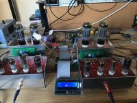
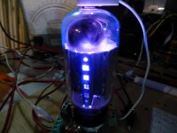
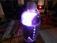
I have reported elsewhere that I was messing around with a Raspberry Pi controlled UL fixed bias PP amp. The primary reason for the micro was to control the bias currents to within 1mA so as to achieve the required current balance in the toroid OPTs, and to mess about a bit with the Raspberry micro’s and the Python programming language.
The design was intended for 6550 tubes, but works for similar tubes such as 6CA7, EL34 KT88 etc. With the 6550 the bias can be varied between 25 and 90mA, but with other tubes it is limited due to the range of the bias voltage.
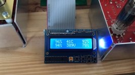
Each power tube is individually calibrated to achieve the desired cathode current. I have added an “emission” parameter that compares the tube current to that achieved by the chosen ‘standard’, (via a LTSpice model) expressed as a %, which should give an idea of tube aging and matching.
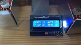
In addition I have added a transconductance measurement facility that will further help matching tubes (expressed here in micro siemens)
I am using Pete Millett’s “Universal PP driver” circuit to drive the power tubes.
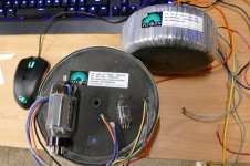
The 4 DAC boards controlling each tube bias have a switch that sets the tube address (the white screwdriver switch on the board)
I have only now completed the two channels to be able to do some listening tests and am pleased with the result.
I’m tempted to leave this in a semi-breadboard condition as it ends itself to ongoing changes!
The design was intended for 6550 tubes, but works for similar tubes such as 6CA7, EL34 KT88 etc. With the 6550 the bias can be varied between 25 and 90mA, but with other tubes it is limited due to the range of the bias voltage.
Each power tube is individually calibrated to achieve the desired cathode current. I have added an “emission” parameter that compares the tube current to that achieved by the chosen ‘standard’, (via a LTSpice model) expressed as a %, which should give an idea of tube aging and matching.
In addition I have added a transconductance measurement facility that will further help matching tubes (expressed here in micro siemens)
I am using Pete Millett’s “Universal PP driver” circuit to drive the power tubes.
The 4 DAC boards controlling each tube bias have a switch that sets the tube address (the white screwdriver switch on the board)
I have only now completed the two channels to be able to do some listening tests and am pleased with the result.
I’m tempted to leave this in a semi-breadboard condition as it ends itself to ongoing changes!
Attachments
Apologies for the delayed response.
There is nothing clever about this amplifier!
The audio circuit is a standard PP in UL mode using Amplimo toroid OPT. The driver is the P Millett universal driver, using 12GN7A pentodes.
The micro controller is a standard Rasperry Pi running Raspian OS. The programming language is Python 3
There may be some uniqueness in the way I am setting up and controlling the bias current which I will try and explain.
Each of the 4 power values has a 10 ohm series cathode resistor, that is used to measure the cathode current via a series of ADC's. The grids of the tubes are controlled by the level shifter (circuit attached; I used a 741 op amp). There are 4 DAC's that control the input to each of these circuits, driving each of the 4 tubes' grids.
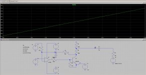
The transfer curve for this circuit is attached. So, for example, if the DAC voltage is 2V the grid voltage is approximately -44V.
In the Python program I use the Koren triode model of the tube (under DC conditions the UL connected pentode will look like it is triode connected). The formulas for this model are readily available from papers or from LTSpice models.
If you apply the model to the level shifter transfer curve you get the second attached curve, that shows the way the anode current varies with DAC voltage for this particular tube.
So, if you decide you want the tubes to run at 40mA, the model predicts DAC output voltage of about 2.1V
Any error between actual and desired current is used to shift the entire curve horizontally so as to zero the error, this new curve is then used to predict the new DAC voltage. Convergence is normally achieved within 2-4 iterations so is quick and fool-proof.
Ic is monitored and is adjusted during audio quiet periods. Whilst music is playing only VB+ and Vg is monitored as a safety check.
Emission % is calculated by comparing the actual tube Ic vs the model's prediction of what it should be at that Vg.
Transconductance (here defined as delta Ic/delta Vg) is measured by varying Vg +- 10% and measuring the change in Ic. This is used only to help match tubes.
There is nothing clever about this amplifier!
The audio circuit is a standard PP in UL mode using Amplimo toroid OPT. The driver is the P Millett universal driver, using 12GN7A pentodes.
The micro controller is a standard Rasperry Pi running Raspian OS. The programming language is Python 3
There may be some uniqueness in the way I am setting up and controlling the bias current which I will try and explain.
Each of the 4 power values has a 10 ohm series cathode resistor, that is used to measure the cathode current via a series of ADC's. The grids of the tubes are controlled by the level shifter (circuit attached; I used a 741 op amp). There are 4 DAC's that control the input to each of these circuits, driving each of the 4 tubes' grids.
The transfer curve for this circuit is attached. So, for example, if the DAC voltage is 2V the grid voltage is approximately -44V.
In the Python program I use the Koren triode model of the tube (under DC conditions the UL connected pentode will look like it is triode connected). The formulas for this model are readily available from papers or from LTSpice models.
If you apply the model to the level shifter transfer curve you get the second attached curve, that shows the way the anode current varies with DAC voltage for this particular tube.
So, if you decide you want the tubes to run at 40mA, the model predicts DAC output voltage of about 2.1V
Any error between actual and desired current is used to shift the entire curve horizontally so as to zero the error, this new curve is then used to predict the new DAC voltage. Convergence is normally achieved within 2-4 iterations so is quick and fool-proof.
Ic is monitored and is adjusted during audio quiet periods. Whilst music is playing only VB+ and Vg is monitored as a safety check.
Emission % is calculated by comparing the actual tube Ic vs the model's prediction of what it should be at that Vg.
Transconductance (here defined as delta Ic/delta Vg) is measured by varying Vg +- 10% and measuring the change in Ic. This is used only to help match tubes.
Attachments

About 10 years ago I entered a design contest sponsored by Microchip and Circuit Cellar Magazine that asked for unique designs that featured their then new 16 bit dsPIC chips. One of their chips was targeted at SMPS controllers. I had been working on state of the art modulated power supplies for cell phone and two way radio transmitters, so I decided to apply the modulated power supply techniques to a vacuum tube amplifier.
The amplifier used many of the same techniques described here. It won one of the category prizes and I was also asked to write a short magazine article about the design.
2007 and 2008 were a very challenging time period in my life with 6 "minor" cancer surgeries, the death of my mother and mother in law with all of the legal BS associated with that, and trying to keep my job in a declining market where my friends were being laid off weekly. I made it to 2014, but the plant that once employed 5000 people is now gone. The amp worked great, and I intended to use it as a development platform for further designs, but sadly it was never taken much further that what is detailed in the magazine article.
Now, 10 years since I designed the original amp, I find myself revisiting the old design and building on it, for a new and much BIGGER amp. I have decided to build a new amp with three conflicting goals:
#1) 1 Kilowatt of total output power (500 WPC) at a reasonable distortion over most of the audio range. Reality dictates that 500 WPC at 20 Hz will need HUGE OPT's and even larger speakers. I have OPT's that are rated for "400 watts at 20 Hz" so that is the low end spec. Reality also dictates that over 100 watts at 20 KHz is unnecessary unless you want to set tweeters on fire.
#2)I want to build an amp that I can carry up the basement stairs by myself if necessary, and would prefer it to all be on one chassis.
#3) I want it to be powered by a US spec 120 volt 15 amp AC outlet. That limits the maximum line power input to 1800 watts, which will restrict the maximum power output to about 400 WPC unless some of the efficiency improvements that I am exploring actually work.
So, I will build a big amp. Whe3ther it will meet all of these design goals remains to be seen. Will it be a conventional PPP design that makes about 400 WPC or a cathode follower output that makes more due to its modulated power supply? Too soon to tell, but what IS certain is that some serious microprocessor control will be needed.
PIC chip? I doubt it. I will likely use a dedicated Arduino compatible like a Teensy 3.6 or possibly an RPi. Both are on the bench right now. Early testing will be on a much smaller amp to limit the risk of fire, explosions, and other generally undesirable but cool stuff. I got a new 4K video camera, so hopefully I will get something cool on video!
Circuit Cellar was bought by Elector, and subsequently returned to being a stand alone publication. All the original articles from the old design contests vanished from their web sites during these transitions. Since I am the author, I am including a copy here.
Attachments
Ufudu I am sure there are some people here who would be interested in seeing/using hardware and your python code if you felt inclined to share it.
The implementation sounds interesting and clever..
The implementation sounds interesting and clever..
#2)I want to build an amp that I can carry up the basement stairs by myself if necessary, and would prefer it to all be on one chassis.
Problem is that probably means most of us wouldn't be able to ! 🙂
Haha, all too true.. 😀
That's why I put my gear on multiple chassis... It does keep noisy stuff away from quiet stuff, but it also makes moving things just a bit easier. Even so I struggle with the GM70 monos and their separate supplies as it is.
That's why I put my gear on multiple chassis... It does keep noisy stuff away from quiet stuff, but it also makes moving things just a bit easier. Even so I struggle with the GM70 monos and their separate supplies as it is.
Ufudu I am sure there are some people here who would be interested in seeing/using hardware and your python code if you felt inclined to share it.
The implementation sounds interesting and clever..
I'm happy to share whatever forum members want, just let me know.
Unfortunately I am not a programmer of any professional status, the only previous time I did any coding was in the late 1970's programming in Fortran and HP Basic!
Therefore the code is not architecturally designed, not properly structured, not documented and has been added to as I thought of things, but I will do my best to explain the code and or hardware as required.
It will look like a dog's breakfast to any professional!
I have attached the full Python code as a txt file to show you what I mean.
Attachments
I hope you will keep us updated on the new amp.
This thing will be a low priority project with no particular time goal. I have had most of the parts for years and so far have been all talk and no action. There will likely be periods of no activity due to other commitments like grandkids and of course other projects. I will start a new thread when I have sufficient info to make it worth sharing.
I found a bad tube (gassy) and took a couple of pictures of it trying to blow my old Fluke 407D power supply. I then set it aside for a meeting with the hammer, but I think maybe it needs to meet with the big power supply and a video camera first?
In the last few weeks I have taken inventory, made some mechanical size and weight measurements and am trying to see if all the required bits like transformers and tubes will fit in my chosen cabinet, and how much it will weigh. The OPT's alone are about 12 Kg each. I have done some tube testing at voltages and currents far beyond the limits of the curve tracer to narrow down my tube choices.
Problem is that probably means most of us wouldn't be able to !
This will be a one off project, but the boards used may wind up as Tubelab products. As with my other boards they can be assembled into an amp any way the builder sees fit including 4 separate boxes, one power supply and one amp per box. This one will be 1 or 2 rack mount boxes.
It does keep noisy stuff away from quiet stuff
A lesson learned from the old magazine project......put the microcontroller inside it's own metal box and properly bypass or filter any I/O that runs into the amp......Ditto the SMPS if used.
Unfortunately I am not a programmer of any professional status, the only previous time I did any coding was in the late 1970's programming in Fortran and HP Basic
I am not either. At the expense of the company I worked for I went to college to get a degree in computer engineering. It taught me that I really wasn't meant to be a programmer. The teacher who taught most of the programming classes I took used to laugh and ask me how I found the longest possible way to program something. I replied that my brain can only process one thought at a time, so I code the same way......that was in 1990, long before the Arduino or RPi's were even a dream.
I took all the knowledge gathered in my college days and distilled it down to a language that I jokingly called C-- . It was basically C with all the stuff that I didn't understand left out. Oddly enough it is remarkably similar to today's Arduino sketches, so close in fact that some of my old PIC "C" code from the 90's will compile and run in the Arduino IDE by only changing the hardware specific references.
Attachments
C -- . .. hilarious! ))
George, I'd advise to approach your goal with 90% of everything. I.e. the OPT would weight 8 KG vs 12, etc etc. Then you just tweak the octet of 6AV5's with your best knowledge, and VOILA! you get it 490 WPC, good enough! ))
(after all, that "Reference" Amp squeezing 35 Wa from thin air with a pair of EL84 - YOURS must be the next Pinnacle!)
George, I'd advise to approach your goal with 90% of everything. I.e. the OPT would weight 8 KG vs 12, etc etc.
Due to recent my current economic condition the budget for this beast is ZERO. For most people that would be the toughest goal, but I have been collecting tube amp parts for a long long time. This means that I must build it from stuff that I already have. I pared down my "stuff" collection by 80 to 90% when I had to move it all, but this beast has always been on my bucket list, so I have most of the necessary "stuff." I might need a small Antek toroid or two, but that is OK.
The OPT choice was made about 10 years ago when I bought the first set of "surplus" Plitrons. Since then I have acquired a second but different set. Conveniently, they weigh 8 Kg (unpotted) and 12 Kg (potted). I am convinced these are identical transformers, so I will use the smaller, lighter set.
you just tweak the octet of 6AV5's
Well, I could call up an army of boys to do a man's job, or I could just go for the biggest sweep tube ever made! I think 4 per channel would do the job as long as you didn't plan on cranking out 500+ watt sine waves from each channel for more than a few minutes at a time. I have seen 525 watts flow through these exact OPT's with 4 X 35LR6's on 650 volts, and it took 2 minutes to provoke a dull red glow in a dark room. I plan to use 36LW6's which are even bigger.
Pushing tubes and OPT's to the limits of their capabilities WILL require some microprocessor control just to shut things down in the event of impending doom. I have seen 6LW6's run away. Once such control is in place, it can be used for all sorts of other cool features.
The point of indecision comes from the choice of topology. It would be far easier to build a conventional PPP amp, and take whatever output power I could get from it at the point of tripping a 15 amp breaker, probably about 400 WPC continuously, 500 WPC for brief periods of time.
I could go for the long shot, a cathode follower output stage with a modulated plate supply which would be far more efficient allowing for more output power from less line current, producing less heat.....it just hasn't been done at this power level....ever! So, in order to help make this choice, I will build a small prototype.
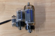
The first picture shows the OPT's with a 12AX7 for size comparison.
The second picture shows a 12AX7, a 6AV5GA, and a 6LW6. Which one would you choose to build a big amp?
Attachments
About 10 years ago I entered a design contest sponsored by Microchip and Circuit Cellar Magazine that asked for unique designs that featured their then new 16 bit dsPIC chips. <snip>
From one Electronic Engineer to another, that is beautiful!
I also like your idea of doing away with the analogue power supply. My thinking was along the same lines. Replace the power supply with a PFC front end SMPS, controlled by the same microcontroller that is controlling your bias voltages.
doing away with the analogue power supply
The "magazine amp" design still used a conventional power transformer and rectifier to produce the HV, the SMPS buck converter just made it variable at an analog rate. Another way of looking at it is that there is a Class D amp delivering 350 V P-P (0 to 350 volt swing) of audio to the plate of a Class A cathode follower which has 60+ dB of PSRR to eliminate small SMPS errors.
Enclosing the cathode follower in an "augmented cathode follower" loop will remove all SMPS imperfections.
augmented cathode follower?
I am currently experimenting with a similar setup on a bigger scale. I prefer to do this in small steps rather than building one big complex design then watching it blow up without knowing why. It currently still uses a conventional power transformer. The transition to full SMPS power will be one of the last steps.
Replace the power supply with a PFC front end SMPS
Most PFC front ends are NOT isolated from the line making them unsuitable for use as power supply. The chips used in these designs don't lend themselves to an isolated design easily, they are designed for capacitor charging.
controlled by the same microcontroller that is controlling your bias voltages.
That was the case in the magazine amp, but so far here there will be the small step concept until everything works, then I start combining things. My programming skils are not the greatest, so each major task will be debugged in it's own controller with some external safeguards until I trust the design. In an amp of this magnitude things can get ugly quickly, and I have no budget to replace expensive parts at this time.
I use these, since they are small (fit into a DIP socket), powerful, and Arduino compatible:
PJRC Store
PJRC Store
- Status
- Not open for further replies.
- Home
- Amplifiers
- Tubes / Valves
- messing about with micro's and tubes..