
Yes - why not. That's a typical schematic with the first 2 stages direct coupled. It should sound pretty decent.
As others have said, you need to wire it up a lot better with proper grounding to the chassis in just one place and the other grounds taken to suitable points. If you run out of space in the chassis it's always possible to take the power supply outboard to another chassis. This enables you to use motor run caps in the power supply and polypropylene cathode bypass caps instead of electrolytics. I'd also use Russian teflon FT-3 coupling caps - cheap and very good indeed. These all take up more space.
Having a separate power supply is always handy for constructors since you can use it for further experiments. You need to figure out a suitable connector if you do - I use Neutrik Speakons but they're only rated to 300v and i don't exceed that. I use 4 pin XLRs for filaments/heaters.
Last edited:
The JE schematic is similar to AN Conqueror; it is a not very smart design.
The sensibility is low..
Please look for the AudioNote KIT one, in my opinion is one of the best circuit for 300B.
Walter
The sensibility is low..
Please look for the AudioNote KIT one, in my opinion is one of the best circuit for 300B.
Walter
That JE Labs Schematic actually looks like a pretty good starting point. You could realize most of it using existing hardware (transformers and such), and if there's something you had to buy, it shouldn't be too expensive.
Okay, the idea of that schematic isn't exactly the most original idea ever invented, but it should work very well.. Who cares if an idea is original, if it's unworkable? And vice versa, of course...
And considering sensitivity? Really, if 0.25Vrms isn't 'nuff for ya... Well, in that case I really don't know, whats the problem with you...
Before you do all that, remove the C6 part (per your schematic; just clip one of its leads). That will drop the gain, may reduce distortion, may improve the sound. Or may not. But super cheap and easy to try.
I told you about Audio Note kit One schematic because it use a half 6SN7 as input stage and a 5687 in Srpp as driver; this tipology is fine to drive at the best the grid of 300B.
In the JE schematic the second stage is is biased with 4.1 mA of bias that for a 6SN7 is very poor; also the Zout is quite high.
Walter
In the JE schematic the second stage is is biased with 4.1 mA of bias that for a 6SN7 is very poor; also the Zout is quite high.
Walter
Before you do all that, remove the C6 part (per your schematic; just clip one of its leads). That will drop the gain, may reduce distortion, may improve the sound. Or may not. But super cheap and easy to try.
Hey thanks for the suggestion. Just tried it and it definitely dropped the gain. Took some harshness off the edge too. It's almost pleasant to listen to now 🙂
Will tide me over while I wait for my parts to be shipped in.
Ok guys, spent the good part of the day figuring out Eagle and measuring the circuit. If there are mistakes, I apologize in advance.
I've tried to be as accurate as possible and replicate the chassis grounds as they are. Any feedback would be appreciated.

This is standard schema, nothing super wrong here. Driver follower is good idea, drives grid stronger.
Step 1; add to c3, c5 paralel these : MKP15-22U/600 MIFLEX - Kondenzator: polypropylenovy | TME Slovakia s.r.o. - Elektronicke sučiastky
Step 2; transformers.
Step 3; maybe no further mods needed
Not sure about supply caps c1,2 80µ , i hope it does not overload rectifier
Before you do all that, remove the C6 part (per your schematic; just clip one of its leads). That will drop the gain, may reduce distortion, may improve the sound. Or may not. But super cheap and easy to try.
Hey thanks for the suggestion. Just tried it and it definitely dropped the gain. Took some harshness off the edge too. It's almost pleasant to listen to now 🙂
Will tide me over while I wait for my parts to be shipped in.
Post #8
..... you can try and remove the cathode bypass cap for the 6SL7.
Maybe I wasn't clear enough in my post but I figured that would help. Glad it did.
Credit definitely goes to you for suggesting it first. Now that the full circuit is up, do you have any other suggestions ? Wouldn't mind trying out more tweaks while I wait for parts to arrive for the rebuild.
Sorry my comment might have come across as snarky. I didn't really want credit, I just wanted you to try the mod without being overpowering and suggest it twice so I am glad someone else suggested it. The person receiving advice about a mod will be more likely give it a try if more than one person suggests it.
What is the anode and cathode voltage of 300b? Which tap are you using on the Hammond Output transformer? And what is your speaker impedance?
What is the anode and cathode voltage of 300b? Which tap are you using on the Hammond Output transformer? And what is your speaker impedance?
Measured with a 5U4G rectifier in place
The anode voltage is 396v
Not sure if I'm measuring at the correct point for cathode, but the voltage at pin 4 to ground is 66.7v
Using the 2.5K tap on the output transformer
My speakers are rated at 8ohms
The anode voltage is 396v
Not sure if I'm measuring at the correct point for cathode, but the voltage at pin 4 to ground is 66.7v
Using the 2.5K tap on the output transformer
My speakers are rated at 8ohms
The value at R5, 100K on cathode of 6SL7?
Also in R4.
The current on 300B is 73mA, the anode dissipation is around 25 watts, that is quite correct.
You can measure the voltage on 900 ohm of 300B directly.
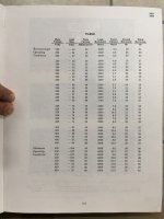
I believe that with a fixed bias you got a better swing on load with that trafo; the Vdc is within specification and with same anode current you have around 30 watt of dissipation; you can remove the 900 ohms and put 1 ohm 1watt as test point.
In attach a beautiful table comes from a W.E. book where are listed lot of output setting for 300B
Walter
Also in R4.
The current on 300B is 73mA, the anode dissipation is around 25 watts, that is quite correct.
You can measure the voltage on 900 ohm of 300B directly.
I believe that with a fixed bias you got a better swing on load with that trafo; the Vdc is within specification and with same anode current you have around 30 watt of dissipation; you can remove the 900 ohms and put 1 ohm 1watt as test point.
In attach a beautiful table comes from a W.E. book where are listed lot of output setting for 300B
Walter
Attachments
Please look for the AudioNote KIT one, in my opinion is one of the best circuit for 300B.
Walter
Is this it?
http://www.audionote.co.uk/downloads/Audio_Note_300B_Kit_1_circuit.pdf
SRPP to drive 300b... not my preference to be honest.
A MU Follower using a cascoded CCS might have lower harmonic distortion (but of course since its a single-ended 300b with no global feedback we can forget anything less than 2-3% THD)
Last edited:
I would suggest that the hands-down "easiest to try" real improvement will be to swap the 6sl7 cathode follower with a MOSFET follower using ZVN0454A.
This is SO easy to just TRY out too.
Simply take off the connection to the 6sl7 follower anode attach it to drain of the MOSFET.... if you are REALLY lazy, leave the 6sl7 follower circuit more or less unchanged (except for de-soldering the anode connection, then attaching it to the MOSFET drain. then just attach the 100k ohm cathode resistor to the source of the MOSFET and the grid connection to the MOSFET gate.
Also, in post 18, looking at the schematic the 300b seems to be missing a grid-stopper.
I agree that you can detach C6 is gain is a bit too much. Also - how are the 300b heaters fed? This really should be 5V DC.
Ian
Last edited:
Yes, it is.
It is very good also under sonic performances with An trafo.
That Srpp is very strong; zout is very low and swing is high.
Walter
It is very good also under sonic performances with An trafo.
That Srpp is very strong; zout is very low and swing is high.
Walter
Measured with a 5U4G rectifier in place
The anode voltage is 396v
Not sure if I'm measuring at the correct point for cathode, but the voltage at pin 4 to ground is 66.7v
Using the 2.5K tap on the output transformer
My speakers are rated at 8ohms
Your speakers are rated for 8 ohms but there is probably dips in the frequency response down much lower giving more distortion at lower frequencies. I suggest trying the 5k tap, the designer was going for maximum power. With a 5k load you will get slightly less power but it will be cleaner and tighter at certain frequencies. Changing the load you may also want to increase the cathode resistance to 1k.
.... and don't forget that SRPP will distort more than a simple triode or MU Follower.
Also, the Zout of the MOSFET follower simply can't be beaten by SRPP.
Lastly, the SRPP sure does provide swing. However the OP has mentioned that he is looking for less gain.
I have used SRPP in pre-amps and Push-Pull designs in the past and they worked well enough. However, it has been my experience that for single-ended designs (where the output stage inherently already distorts) it is just a modest choice.
I suggest the OP look at Tube-Lab.com for some inspiration. George had tried all of these things we discuss. Of course all this is simply advice. If their source is poor, then nothing either of us suggest will matter.
Last edited:
I would suggest that the hands-down "easiest to try" real improvement will be to swap the 6sl7 cathode follower with a MOSFET follower using ZVN0454A.
This is SO easy to just TRY out too. . . . .
Wigggly fingies typo? I think you mean ZVN0545A.
I agree. Easy stuff to try is a shame not to try.
- Status
- Not open for further replies.
- Home
- Amplifiers
- Tubes / Valves
- I bought a 300b amp from a local builder... is it worth keeping ?