Hi everyone, first post on this forum.
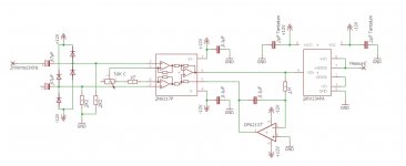
I've build the following circuit on my breadboard to test the INA217 and DRV134 as a mic pre:

The circuit is powered with my lab power supply, which gives me 12V dual max.
The INA217 on its own works really well. When I put a 7mVrms/1KHz signal in on the positive input, it outputs 5.54Vrms at maximum gain which gives me 58dB of gain (sweet!).
When I added the DRV134, it worked as it gave me the same 5.54Vrms at its positive output, but after a minute or so it blew up and magic smoke started coming out of it 😛
I'm a bit puzzled why this happened as I don't think I exceeded any maximum ratings. I also double checked my wiring, and everything seems to be right. Maybe there needs to be a resistor between the INA217 and the DRV134 to limit the current, but the DRV134 has 10k input impedance so this shouldn't be a problem? Maybe the tantalum bypass caps are causing oscillation or something?
I hope someone here can tell me what the problem is or give me a clue, as I want to avoid blowing up another one as these are a bit expensive 😀
Thanks!
I've build the following circuit on my breadboard to test the INA217 and DRV134 as a mic pre:

The circuit is powered with my lab power supply, which gives me 12V dual max.
The INA217 on its own works really well. When I put a 7mVrms/1KHz signal in on the positive input, it outputs 5.54Vrms at maximum gain which gives me 58dB of gain (sweet!).
When I added the DRV134, it worked as it gave me the same 5.54Vrms at its positive output, but after a minute or so it blew up and magic smoke started coming out of it 😛
I'm a bit puzzled why this happened as I don't think I exceeded any maximum ratings. I also double checked my wiring, and everything seems to be right. Maybe there needs to be a resistor between the INA217 and the DRV134 to limit the current, but the DRV134 has 10k input impedance so this shouldn't be a problem? Maybe the tantalum bypass caps are causing oscillation or something?
I hope someone here can tell me what the problem is or give me a clue, as I want to avoid blowing up another one as these are a bit expensive 😀
Thanks!
Hi,
if used in asymmetrical mode one of the outputs need to be grounded.
It seems You left the inverting output floating.
Keep in mind also, that only in differential mode the output offset is small, even if the offset of each output can be considerably high.
In asymmetrical mode the output offset can be reduced by a couple of lytics (bipolar type, see the application suggestion in the DS).
jauu
Calvin
Thanks Calvin for your reply
Indeed I would need to ground the inverting output, but does leaving this pin floating damage the IC when measuring on the non-inverting output with a scope? I want to connect both pins to an XLR for symmetrical use, but someone might connect an unbalanced cable to it and that shouldn't damage the circuit.
I think I have found the cause... I've connected the negative supply bypass tantalum cap the wrong way. 😱 It probably shorted to ground...
I'm going to replace them with non-polar 1µF film caps for the next try.
I've seen a schematic where they put a 100ohm resistor in series between the INA217 and the DRV134. But is that necessary?
Hi,
if used in asymmetrical mode one of the outputs need to be grounded.
Why so??
As long as the sense line is tied back to the output (as it is in his schematic), I see no reason why this would damage the IC or hinder performance at all. In fact, I would recommend not do it so the 50 ohm build-out resistor is not connected directly to ground.
Dave.
Last edited:
- Status
- Not open for further replies.