Hi, Mooly.
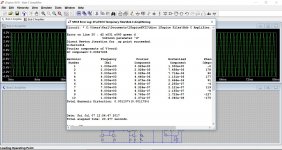
Simulation shows two THD figures at the LTSPICE .FOUR analysis. What's the difference in these two thd results xxxx% (xxxx% ).
Simulation shows two THD figures at the LTSPICE .FOUR analysis. What's the difference in these two thd results xxxx% (xxxx% ).
Last edited:
It has other problems though... unstable with no input connected and very component value critical (all in the sim of course)
Lack of base stoppers seem to be a major contributory factor here.
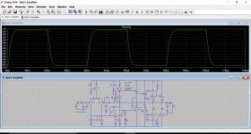
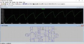
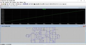
Latest play around, this is performing much better stability wise. Bias in the last shot now at 60ma per pair.
Lack of base stoppers seem to be a major contributory factor here.
Latest play around, this is performing much better stability wise. Bias in the last shot now at 60ma per pair.
Attachments
Hi, Mooly.
Simulation shows two THD figures at the LTSPICE .FOUR analysis. What's the difference in these two thd results xxxx% (xxxx% ).
Here:
http://www.diyaudio.com/forums/soft...pice-iv-beginner-advanced-42.html#post5121252
and here:
http://www.diyaudio.com/forums/soft...pice-iv-beginner-advanced-42.html#post5121327
Is that worth the debugging effort for a design with such poor performance and seen unstable in simulation ?
I think so, yes.
In Bobs own words the amplifier is described as 'basic' (at least at the start of the relevant text) and it is then used as a building block to show various techniques.
I wouldn't want to speak for Bob, but I doubt he had it in mind as a completed project ready for the real world. To do that needs a bit of polishing as I have attempted here.
Its all fairly basic stuff, reduce the gain to unity at DC, add a suitable input filter and decide on a suitable input impedance. Attend to the output stage re components required for stability with real loads.
It seems fairly decent as it stands now.
I have much simpler that gives in LTspice:
0.0001% thd at 1khz 4volt peak in 8 ohm.
Stable without any fiddling in LTspice, no oscillation whatsoever. Thermally rock stable design.
At 20Khz the worst thd ( 0.007% ) is at amplitudes around 1volt peak. Better at small amplitudes and better at large amplitudes ( thd 0.002 at 30volt peak ).
0.0001% thd at 1khz 4volt peak in 8 ohm.
Stable without any fiddling in LTspice, no oscillation whatsoever. Thermally rock stable design.
At 20Khz the worst thd ( 0.007% ) is at amplitudes around 1volt peak. Better at small amplitudes and better at large amplitudes ( thd 0.002 at 30volt peak ).
I have much simpler that gives in LTspice:
0.0001% thd at 1khz 4volt peak in 8 ohm.
Stable without any fiddling in LTspice, no oscillation whatsoever. Thermally rock stable design.
At 20Khz the worst thd ( 0.007% ) is at amplitudes around 1volt peak. Better at small amplitudes and better at large amplitudes ( thd 0.002 at 30volt peak ).
Please share it mchambin.
I think so, yes.
In Bobs own words the amplifier is described as 'basic' (at least at the start of the relevant text) and it is then used as a building block to show various techniques.
I wouldn't want to speak for Bob, but I doubt he had it in mind as a completed project ready for the real world. To do that needs a bit of polishing as I have attempted here.
Its all fairly basic stuff, reduce the gain to unity at DC, add a suitable input filter and decide on a suitable input impedance. Attend to the output stage re components required for stability with real loads.
It seems fairly decent as it stands now.
Mooly, thank you for your efforts. Like I mentioned before in this thread I'll be trying out the mods this weekend.
To Boscoe.
Sure I will share. It is a revamp of an amp I published years ago.
Search for my "op amp based amplifier" posts.
http://www.diyaudio.com/forums/solid-state/198734-another-op-amp-based-amplifier.html
Now, it is actualized using
LTC6090 high voltage op amp
2SA1943/2SC5200
2SC4793/2SA1837
+ - 50v rails
8 ohm load
Two 0.33 ohm at output.
Two 100 ohm at output transistors e b.
Set for voltage gain +3 ( 1k 2k )
Set CCS currents at 7mA
Last edited:
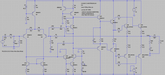
I had a play with this and have attached the .asc if anyone wishes to continue. I made a few quick changes but found the stability might need looking at more closely. The last shot shows something going on but whether it is an artefact of the sim I wouldn't like to say. However other tweaks I tried also showed stability issues (such as decoupling the vbe multiplier).
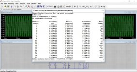
Hi Mooly, I tried the LTspice circuit you posted in #20. I'm afraid the distortion and the instability have to do with the bias current setting at the output stage. The output stage seemed to have been biased at 18mA per transistor as is. I then bumped it up to 66mA per transistor, and the distortion improved by 10dB, at 0.0009%, 1KHz 3.925Vpk. The instability is no longer there at this higher bias current.
I'll try to do some loop gain plot.
Mooly, thank you for your efforts. Like I mentioned before in this thread I'll be trying out the mods this weekend.
Your welcome 🙂 and its always fun tweaking a design.
(Remember to use a bulb tester)
Hi Mooly, I tried the LTspice circuit you posted in #20. I'm afraid the distortion and the instability have to do with the bias current setting at the output stage. The output stage seemed to have been biased at 18mA per transistor as is. I then bumped it up to 66mA per transistor, and the distortion improved by 10dB, at 0.0009%, 1KHz 3.925Vpk. The instability is no longer there at this higher bias current.
I'll try to do some loop gain plot.
There seemed to be a few issues at work for some reason. I'd say any amp should really be stable throughout the normal range of bias current, including down to zero.
Even the resistor values around the current mirror, and the LTP degeneration seemed a bit fussy as well.
This was the latest variation on a theme (attached)
Attachments
That certainly seems a great improvement 🙂 I added some rail ripple to the positive side.
This kind of details makes differences in an amplifier project from text books to a commercial one. It is used by Sony SE amplifier and also Yamaha amplifiers and I really tested it and works very well in pratice.
Thank you for your great work teaching to use LTSpice.
Last edited:
a capacitor across a Zener is very inefficient - the zener has very (or should be biased to) low dynamic Z making the RC time constant for line ripple require a very large C
I would increase the Zener current, 1 ma is just too low for good noise
and I would split the bias R and use a bypass C from the midpoint, giving much larger R, needing less C, or give better PSRR for same C
I would increase the Zener current, 1 ma is just too low for good noise
and I would split the bias R and use a bypass C from the midpoint, giving much larger R, needing less C, or give better PSRR for same C
- Status
- Not open for further replies.
- Home
- Amplifiers
- Solid State
- Please help with issues I'm having with my Bob Cordell amplifier implementation.