Hi all,
I've been brewing up this idea in my head for a couple of months now and I've finally had the time to sit down and work on it. This thread will hopefully document the progress and challenges of the design and build.
---
I am designing a Fender 5F6A Bassman clone that, with the exception of the magnetics, is contained to a single circuit board and will require limited point to point wiring. Given an assembled circuit board, I would like to be able to assemble the completed amplifier in less than 5 minutes. Note: This is just a Bassman head that can be paired with a cab of your choice.
Point-to-point wiring/soldering isn't difficult, but it is tedious. You will notice that most modern products try to do away with this kind of construction if possible. Errors are much less likely when all of the "wiring" is done via traces on a circuit board.
I think simplifying the build of the amp might attract DIYers who might be interested in building an amp but might have been put off by the labor and complexity of a point-to-point amp. If there is enough interest, I am planning on making a few runs of boards for people to purchase. I will release all my electrical and mechanical design files as well.
I do not have much to show at the moment but I intend to work on it quite a bit in the coming months.
Let me know what you think of the idea and if you'd be interested. Thanks!
---
6/30/2017
-Magnetics arrived (toroidal power transformer, output transformer, choke)
7/4/2017
-Schematic drawing in KiCad (KiCad EDA) completed
-Parts selection in progress
-Creation and association of PCB 'footprints' with selected parts in progress
-PCB layout not started
Happy building!!
Points I would have considered:
6L6 5881 sockets cook PCB. Yes, a million factory amps do it this way, and are OK for a few years, but not for 60 years (even 20 years). Oversize sockets, high-grade PCB stuff, and ample cab cooling improves things some.
There is no good way to run AC heaters on PCB (can't twist). My Ampeg VT-40 had heavy hum, masked by the open-back cabinet. Peavey tends to run DC heat. While excess hum is bad, IMHO a "zero" hum amp is also wrong.
Can't really disagree with the amount of wiring in a Fullerton 5F6a. It worked for Leo because his women did a few steps over and over for years, and got real good at it. Assuming that wiring never fails, the eyelet-board makes it real easy to later replace a cap or resistor (compare with the earliest Fenders or any P-2-P radio guts). The tradeoffs should be different for hobbyists.
Thank you for your encouragement and for your thoughts.
Based off your recommendation, I will definitely use larger tube sockets. Additionally, I hope to use 2oz copper FR4 board and if not, plain old 1oz FR4 which still does pretty well with heat.
I'm on the fence about using DC heaters. I'm considering regulated DC for the first 12AX7, and possibly the second. Though you can't twist traces, I will run the remaining AC heaters as differential pairs, likely one on the top side and one on the bottom. I hope this will keep noise low.
Just DC-elevate the heaters, and you shouldn't have problems with heater hum. Sometimes elevation can be more effective than DC heaters.
Personally, I would run the power tubes completely off the board, and mount their sockets directly on the chassis. There's very little wiring at the power tubes to worry about.
Sent from my phone. Please excuse any typpos.
Personally, I would run the power tubes completely off the board, and mount their sockets directly on the chassis. There's very little wiring at the power tubes to worry about.
Sent from my phone. Please excuse any typpos.
HUH??? WHY would that be???. Hum is unpleasant to my ear.While excess hum is bad, IMHO a "zero" hum amp is also wrong.
Thanks for the suggestions. I would hope that a 'DC elevated' AC heaters would be good enough. This should make the leakage current from heater to cathode essentially 0. Any induced 60Hz would probably be a product of poor circuit board layout. That being said, a low drop out regulator like the MIC2941A can be easily configured to supply regulated DC power to the preamp tube. Perhaps I will layout the board to be configurable for both (at least for the first revision). If noise seems to be an issue, I can enable the regulator.
I feel like it's one of those things that's tough to really know until you try it out. There are signal integrity software packages and calculations that could be made, but I think that would be more effort than it's worth.
Thank you.
I feel like it's one of those things that's tough to really know until you try it out. There are signal integrity software packages and calculations that could be made, but I think that would be more effort than it's worth.
Thank you.
Having worked for some considerable time as an amp designer and builder, I can assure you the dc-elevated heaters will be more than enough. I've also sometimes seen DC heater supplies actually inject more noise, although it could ultimately be filtered out.Thanks for the suggestions. I would hope that a 'DC elevated' AC heaters would be good enough. This should make the leakage current from heater to cathode essentially 0. Any induced 60Hz would probably be a product of poor circuit board layout.
Layout, and more specifically grounding scheme becomes even more critical.
It gives some intermodulation to the signal. For good or bad we are used to hearing amps with artifacts that on the surface would seem bad.
Seconding this idea. Twisted ac heaters. Tube depot uses a pcb board for the 5f1 and 5e3, 1 thing i like is different spacing for different sized caps built into the traces.
"Personally, I would run the power tubes completely off the board, and mount their sockets directly on the chassis. There's very little wiring at the power tubes to worry about. "
"Personally, I would run the power tubes completely off the board, and mount their sockets directly on the chassis. There's very little wiring at the power tubes to worry about. "
> Just DC-elevate the heaters, and you shouldn't have problems with heater hum.
There are many causes of hum. Elevation and twisting attack *different* problems.
Very low level hum is not offensive; it is "the sound of electricity". An utterly hum-free amp sounds artificial, phony. You are free to disagree.
There are many causes of hum. Elevation and twisting attack *different* problems.
Very low level hum is not offensive; it is "the sound of electricity". An utterly hum-free amp sounds artificial, phony. You are free to disagree.
I have seen twisted wires in commercial PCB amps and do not want to discredit the design decision the engineers made there. At the same time, I wonder if that was more of a cost saving measure than a performance thing. They might be able to get away with using a cheaper single sided CEM type board if they take that approach. I'm not sure!
I would say it's okay to have some hum, but we shouldn't design the amp with the intention of introducing hum.
I would say it's okay to have some hum, but we shouldn't design the amp with the intention of introducing hum.
Very true.> Just DC-elevate the heaters, and you shouldn't have problems with heater hum.
There are many causes of hum. Elevation and twisting attack *different* problems.
OK, I'll then take up my constitutional right to disagree. 🙂 It's actually only the sound of AC, not electricity, per se. And I hope you realise that you've called my tube amps, used by a good many players, as sounding phoney. Ouch, that hurts!Very low level hum is not offensive; it is "the sound of electricity". An utterly hum-free amp sounds artificial, phony. You are free to disagree.
IMHO the intention of the design should be absolutely no hum. With a decent layout which includes good grounding, that is very achievable.
Last edited:
Thanks for all of your input. Here's a technical question regarding proper (and safe) earthing:
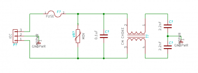
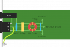
I'm going to integrate an AC line filter onto the board because, well, why not. (Line voltage will then leave the board, go to transformer, and come back.)
The attached picture (I think) should speak for itself. Is it an acceptable scheme?
Protective earth will be connected to the chassis as close to the IEC inlet as possible (not actually sure if this is required/matters). After the filter components, protective earth will be connected to circuit/signal ground at ONE place. I'm probably going to do star grounding to some extent on the board, making sure to keep preamp, output tubes, and power supply return paths independent.
Thanks.
Attachments
You learn something every day.
First, one that I understand. DHT people generally prefer AC to DC heated filaments - at least until the DC heater provides a high impedance (current source w/ limited voltage) across the the audio band (and then some). And stops coupling all sorts of HF crap straight into the heaters.
Rod Coleman sells the current DIYAudio approved version. (See hereabouts)
The second I just stumbled on the other day and relates to the modulation of guitar signal by the AC ripple.
The Strange Effects of AC Ripple on a Class AB Power Amp
Most interesting.
I will, with a "but". Actually two "buts".You are free to disagree.
First, one that I understand. DHT people generally prefer AC to DC heated filaments - at least until the DC heater provides a high impedance (current source w/ limited voltage) across the the audio band (and then some). And stops coupling all sorts of HF crap straight into the heaters.
Rod Coleman sells the current DIYAudio approved version. (See hereabouts)
The second I just stumbled on the other day and relates to the modulation of guitar signal by the AC ripple.
The Strange Effects of AC Ripple on a Class AB Power Amp
Most interesting.
VERY interesting! They did a quite good scientific analysis of the power supply waveform and the resulting effect on the signal output of the Fender Bassman amp; then they completely dropped the ball when it came to their "conclusion""the modulation of guitar signal by the AC ripple.
The Strange Effects of AC Ripple on a Class AB Power Amp
Most interesting.
"in terms of sound the amplifier is no longer recognizable. Its tonal characteristics are completely different. Touch sensitivity - zero. Crisp dynamic overtones - zero. As Schmidt and Westphal put it, the WILDCAT became more like a kitty cat."
NO measurement. NO scientific analysis like a double-blind test of results with and without the ripple. Just a bunch of subjective "kitty cat" analogies. How disappointing. They may have something there, but they need to complete the experiment objectively.
You hit the nail on the head. Guitar amps make many noises that are quite utterly horrid (just ask the generation that grew up before Jimi Hendrix and Cream). But each of those nasty noises also has fans, people who expect and love it.For good or bad we are used to hearing amps with artifacts that on the surface would seem bad.
One of the most bizarre things I've run into was praise for amps that "note switch". Some amps, when heavily overdriven, exhibit a behaviour where the pitch of the sound emitted by the amp appears to flip randomly between two different values - and some people, apparently, take this as an indicator of amp greatness. 😱
As a musician, my entire function is to play the right note(s) at the right time. An amp that decides to randomly change the note it's emitting is, for me, an utterly useless amp. It's the kind of amp that should be beaten forcefully with a sledge-hammer until it falls apart. Or, if you're feeling kind and charitable, taken apart and redesigned, so it stops "note switching". 😡
I'm with AquaTarkus and Dotneck on the hum issue. IMO, the right amount of hum is no hum. (Or, more exactly, any hum present must be below the threshold of audibility.)
Enough about hum, now let's talk about heater power. Back when 6.3V, 50 or 60Hz AC became the standard for heater power, it was the only option.
It was a horrible option, as anyone who knows anything about electromagnetism can tell you. Running amperes of AC current through wires right next to a sensitive audio amplifier is an act of lunacy, unless there is no other alternative, and in that case, it is an act of desperation. In the earliest days of AC power to homes, there was no alternative.
Necessity is the mother of invention. The desperate act of running lots of AC power at audio frequencies right next to sensitive audio amplification devices forced people to do the best they could to compensate. They invented tightly twisted heater wiring, pushing the heater wires into chassis corners, carefully avoiding "loops around the valve socket" and all the other tricks that made the best of a bad job. A very bad job.
This state of affairs was true for a long time, in fact, for many decades. Sure, along the way we got silicon diodes and huge electrolytic caps, but the spiky diode currents and triangular ripple voltages created nasty buzzes when used for heater power. Buzzing is even worse than humming.
We also had linear DC regulators. The small and affordable ones didn't cope well with the amount of heater power a box full of valves need. They got hot, they needed huge heatsinks, they overheated and shut down.
All this started to change maybe ten or fifteen years ago, when little switch-mode power supplies started to increasingly replace huge, heavy, traditional "big iron" power supplies in most consumer devices.
Now these little SMPS are everywhere, and they're small, light, efficient, reliable, and capable of putting out startling amounts of pure, clean DC power without strain. (How big and heavy would a traditional power supply have to be to match the soapbar-sized 80-watt "brick" that powers your laptop?)
I have used thrift-store wallwarts (small switch-mode power supplies) on valve heaters a few times now, and experienced no negative consequences whatsoever. No audible hum or buzz, no visible HF noise when 'scoping the amp output; I didn't poke my eye out with that, the bedbugs didn't bite, the big bear didn't get me. 🙂
I did initially have worries that I would see switching-frequency "hash" on the amp output, but it turned out to be a non-issue, as long as I keep the SMPS at least several inches from the amp's input wiring.
IMO, using an SMPS with a nice clean DC output is a much saner way to power heaters in the year 2017. We're no longer forced into the desperate act of running amps of AC through a high-gain audio amplifiers guts. Now we have a much, much, better alternative.
-Gnobuddy
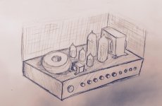
Did a little concept drawing. Nothing much. Trying to figure out form factor. Went off on a tangent on a bunch industrial design details.
I'm shooting to use the Hammond 1441 chassis with 1451 perforated cover.
Tubes sockets will be board mounted and holes will be drilled in the top of the enclosure to allow them to "breathe" under the perforated cover. I'm using a 100VA 300-0-300V toroidal transformer with a Hammond 1760K output transformer.
More meaningful updates soon.
Attachments
had a jansen bassman 60 on the bench last year (fender clone) this had pcb mounted tube sockets and over the last 25 years it has had to have every single pin on the 6l6's re-soldiered at one time or another due to vibration and had pulled the tracks clean off the pcb.
this was a hard working amp doing lots of gigs spent lots of time bouncing round in a trailer too.
BUT if the sockets had been mounted to the chassis I think it would have been way more reliable
this was a hard working amp doing lots of gigs spent lots of time bouncing round in a trailer too.
BUT if the sockets had been mounted to the chassis I think it would have been way more reliable
had a jansen bassman 60 on the bench last year (fender clone) this had pcb mounted tube sockets and over the last 25 years it has had to have every single pin on the 6l6's re-soldiered at one time or another due to vibration and had pulled the tracks clean off the pcb.
this was a hard working amp doing lots of gigs spent lots of time bouncing round in a trailer too.
BUT if the sockets had been mounted to the chassis I think it would have been way more reliable
Thanks for this. I'm curious were these double side or single sided board? Plated through holes?
In any case, it is a valid concern, especially for gear on the road.
Perhaps the best solution here is to use a chassis-mount tube socket with PC board pins. The mounting flange would be on the inside of the enclosure. This way the board can be installed with the sockets already soldered to them. Fastening down the sockets could be done with a mech screw and nut. Larger diameter holes can be drilled in the board to allow for a screwdriver/nutdriver.
- Status
- Not open for further replies.
- Home
- Live Sound
- Instruments and Amps
- Build Log: 'New Wave' Fender 5F6A