This amplifier is difficult to repeat to radio amateurs. In his winding, he used a wire in Kel-F ( TECAFLON,Teflon-3) insulation and rather thick insulation. I've never seen such on sale. Although I was told at the plant that they can make a special double-sealed enamel wire plus Teflon-4 insulation by special order. Apparently, Bereskin in 1958 had a rich and ambitious customer.
thanks, i have decided that i am not going to make any tube amp of this magnitude and scale.....
Tony, the cover is good. Did you do it yourself? The coloring of the color is also good, not glamorous.
Looking good.
Shoog
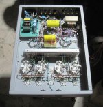
thanks......output stage is almost done....i am taking it slow...
good ideas flow in the morning when i wake up....😀
Tony, the cover is good. Did you do it yourself? The coloring of the color is also good, not glamorous.
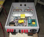
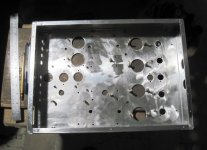
you mean chassis? yes, i made it from 1.5mm thick aluminum sheets
and bent using box benders in a local shop...
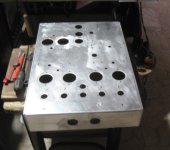
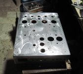
all holes were drilled by me using combination of drill bits,
hole saws and step drill bits....
powder coating light textured grey finish...
flap sand paper wheels attached to a baby grinder was
used to remove burs and rough edges from the drilling
and hole cutting....
Attachments
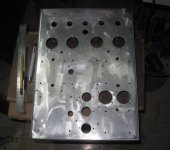
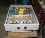
some bolts were pre installed and exposed threads wrapped in masking tape prior to powder coating,
this is necessary so that safety grounds can be connected to chassis....
this is necessary so that safety grounds can be connected to chassis....
Tony, good work.
6AG7 (6П15П) can be used in such a driver for load resistance R5, R6 - 68kOhm as in the diagram?
http://www.diyaudio.com/forums/atta...-tonys-tabor-amp-clone-build-log-img_0028.gif
Or the resistance should be reduced, which too will increase the depth of local feedback from the output tetrodes.
6AG7 (6П15П) can be used in such a driver for load resistance R5, R6 - 68kOhm as in the diagram?
http://www.diyaudio.com/forums/atta...-tonys-tabor-amp-clone-build-log-img_0028.gif
Or the resistance should be reduced, which too will increase the depth of local feedback from the output tetrodes.
as i have committed myself to 7 pin sockets, i am going to use 6bc5 or 6gk5 which i have plenty of...
Tony, I'm not talking about the sockets (base) or replace the tube with analogs. How to adjust the depth of local feedback in this driver?
Do you make your own amplifier in this or similar diagram?
http://www.diyaudio.com/forums/atta...-tonys-tabor-amp-clone-build-log-img_0028.gif
Do you make your own amplifier in this or similar diagram?
http://www.diyaudio.com/forums/atta...-tonys-tabor-amp-clone-build-log-img_0028.gif
Last edited:
That's been discussed before in this thread.
Tony makes his own clone of the Tabor, however without the common current source in the output stage.
So it's far from a Tabor.
Tony makes his own clone of the Tabor, however without the common current source in the output stage.
So it's far from a Tabor.
Tony, I'm not talking about the sockets (base) or replace the tube with analogs. How to adjust the depth of local feedback in this driver?
Do you make your own amplifier in this or similar diagram?
http://www.diyaudio.com/forums/atta...-tonys-tabor-amp-clone-build-log-img_0028.gif
As I pointed out before this design has almost 100% local feedback around the finals and there is no straightforward method of reducing this. Something along the lines of the Baby Huey might be adapted - but the Huey uses triode drivers so the ratios would be very different.
Shoog
I do not like the source of current either. The driver is very good. I want to make a similar driver in the project on four EL509That's been discussed before in this thread.
Tony makes his own clone of the Tabor, however without the common current source in the output stage.
So it's far from a Tabor.
Last edited:
From my practice, I know that you can always find a way out of any difficult situation. For example, one of the simple options, you can put another resistor in parallel with the driver as a divider.As I pointed out before this design has almost 100% local feedback around the finals and there is no straightforward method of reducing this. Something along the lines of the Baby Huey might be adapted - but the Huey uses triode drivers so the ratios would be very different.
Shoog
that maybe, but that is not the scope of this thread and i am sure glad
that you opened you your own thread....
that you opened you your own thread....
As I pointed out before this design has almost 100% local feedback around the finals and there is no straightforward method of reducing this. Something along the lines of the Baby Huey might be adapted - but the Huey uses triode drivers so the ratios would be very different.
Shoog
reason why no global negative feedback was needed and applied.
i have done such an arrangement with 8 kt88 in push-pull triode wired,
i made provisions for gnfb connections but listening to the finished amp
found no need for such...
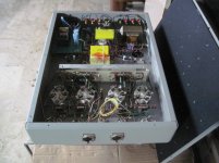
today's progress, will be fabricating a front end psu and input board to complete
assembly, now designing the CCS for input LTP tails and psu CCS...
will attach pictures later...
assembly, now designing the CCS for input LTP tails and psu CCS...
will attach pictures later...

- Status
- Not open for further replies.
- Home
- Amplifiers
- Tubes / Valves
- Tony's TABOR amp clone wannabe build log.....