That said, the idea that the energy sloshes in and out of a short interconnect cable at audio frequencies and that this is somehow an issue is misguided at best. The cable will present a capacitive load on the cable driver. For a common 1-2 m cable, the cable is responsible for maybe 100 pF (= 80 kΩ reactance @ 20 kHz). This is not a cause for concern.
Tom
I'm glad to have another myth de-bunked. Thanks Tom.
I wish my friend would have known you when he was 'rolling' FIM, MIT, and Nordost cables. I also wish we would have done our comparison blind, but at the time we didn't know any better. Information like this might have saved him thousands of dollars!
Best regards,
That would work. You could also use microphone cable. Use one conductor for the centre conductor, the other for the shield. Terminate the cable shield at one end (the transmitting end). That would be your standard "audiophile" interconnect cable setup. Just add directional arrows... 🙂
You'll probably get better performance if you use one conductor for the shield connection and connect the shield at both ends as that reduces the ground impedance. Of course then the cable won't be audiophile approved as it won't have the directional arrow.😉
Tom
by chance i just stumbled upon this illustration. I think it's kind of what you described. What would be the idea of connecting the shield on one side only?
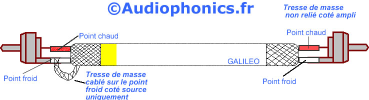
This is called a "pseudo-balanced" line. Extreme audiophiles add a 10k resistor between plug and shield.
I'm thinking of getting a Galaxy chassis from modushop in italy for my 3886dr amp. Does anyone know what's the difference between the version with aluminum covers and the version with steel covers ..... well apart from one being made of steel and the other .... 🙂
Would one be stiffer or more rigid than the other? Any other considerations .... apart from price and looks?
https://diyaudiostore.com/collections/galaxy
Would one be stiffer or more rigid than the other? Any other considerations .... apart from price and looks?
https://diyaudiostore.com/collections/galaxy
I have several modushop chassis' and the ones with aluminum covers are easier to drill especially if you need precise holes location.
Thanks, that's a good point.
I was also wondering if the steel version would be stiffer.... but then again the aluminum is thicker. I just don't want it to bend and all the stuff i'll put in there will have quite some weight.
I was also wondering if the steel version would be stiffer.... but then again the aluminum is thicker. I just don't want it to bend and all the stuff i'll put in there will have quite some weight.
For heavy duty I would recommend to order a pierced baseplate for your chassis especially if you plan to put there 200+VA transformer.
by chance i just stumbled upon this illustration. I think it's kind of what you described. What would be the idea of connecting the shield on one side only?
That's exactly what I had in mind. Not sure it matters – it probably doesn't – but the source is commonly connected at the left end of that cable. The directional arrows on the cable would point left to right in your illustration.
This is called a "pseudo-balanced" line. Extreme audiophiles add a 10k resistor between plug and shield.
Actually, pseudo-balanced or pseudo-differential takes an unbalanced source and connects it to a balanced input. Like this:
An externally hosted image should be here but it was not working when we last tested it.
Tom

That's exactly what I had in mind. Not sure it matters – it probably doesn't – but the source is commonly connected at the left end of that cable. The directional arrows on the cable would point left to right in your illustration.
Tom
So that's just a common setup that people use and nobody really knows why? 🙂
No, people do know why. Some just don't believe it makes any difference. Some (and I'd agree with these folks) believe that connecting the shield at both ends is better as it lowers the ground impedance.
Suggestion: Rather than collecting multiple "opinions" and averaging them to find "the truth", I suggest looking at the physics involved and the arguments used for one cable versus another. The physics is maybe slightly more involved that Ohm's Law, but not by much.
Rane Corp. is a good source of white papers on things involving grounding. As is "The G Word" (published in EDN and Linear Audio). Ralph Morrison, "Grounding and Shielding in Instrumentation" is a worthwhile read as well.
Tom
Last edited:
thanks for your reply!
i wasn't actually collecting opinions to average them. it's more that i'm interested to hear why people do certain things. it's just out of curiosity and a desire to understand stuff before i do it.
i've only spent a few weeks reading and posting in this forum and i was lucky enough to find a few people who have tons of knowledge and it's great to learn from them.
thank you for the reading suggestions you provided .... i'm all set up for a busy reading sunday.
i wasn't actually collecting opinions to average them. it's more that i'm interested to hear why people do certain things. it's just out of curiosity and a desire to understand stuff before i do it.
Fair enough. I'm sorry if I misinterpreted. I do recognize that there's a significant learning curve if you want to be able to understand the various design tradeoffs. Those of us who started young have a significant advantage there.
Tom
... Those of us who started young have a significant advantage there.
Tom
Well...
Even more than 30 years in pro audio don't help when posting before first coffee 🙄
Well...
Even more than 30 years in pro audio don't help when posting before first coffee 🙄
True that. Or while jet lagged as is currently my case. 🙂
Tom
Alright. The jetlag isn't completely gone, but I am one cup of coffee into my day and the second cup is poured and approaching drinking temperature. Let me try to be a bit more helpful.
The common audiophile cable connection scheme is shown below.
The source is typically on the left and the load on the right. The cable will have directional arrows pointing left to right.
This scheme is used in an attempt to deal with electromagnetic interference. I believe this is the common line of thinking:
The shield acts as a Faraday cage and should terminate all external fields to ground. If the shielding is 100 % (it isn't in practice) no voltage should be induced in the centre conductor. That's the goal of shielding after all. The impedance of the shield tends to be low, thus it is rather difficult to establish any significant error voltage across the shield. So as long as the cable is reasonably short and/or the external EM fields reasonably low, the common coax cable setup works just fine.
For the second point, it is true that ground loops will cause some current to flow in the ground net. Ground loops are exceptionally difficult to avoid, so you have to deal with them. The best way to avoid ground loops is to use an optical connection (those with noise in their USB DAC setups take note). There will be some coupling between the centre conductor and the cable shield, but unless the load impedance (input impedance) is very high (say 1 MΩ) the 100 pF or so of a common interconnect won't cause issues within the audio band.
Thus, while the two claims above are valid, I don't believe they are a huge cause for concern.
The audiophile cable setup attempts to deal with these two "issues" by breaking the shield, thereby avoiding any ground current in the shield. The shield is connected to the source, which is assumed to be the quietest ground available, thereby minimizing the amount of crap coupled to the centre conductor. Since the ground reference is still needed to establish the input voltage to the load, the ground is carried by a separate conductor.
I think this approach is flawed for a few reasons. First off, the shield is now not 100 % and can never be. So it won't provide as effective shielding. Also the impedance from the shield to ground just doubled as any EMI imposed on the shield has to flow to the source. Some will argue, "but, but it's twisted pair so the EMI should cancel out". That would be true if the connection was balanced/differential and the input/output impedances on the signal pair was equal. That's not the case for an unbalanced/single-ended connection. Furthermore, leaving the shield unterminated at one end creates an antenna, which can radiate all sorts of stuff and is probably at resonance at some frequency where the cable is then more susceptible to EMI. To make matters worse, the cross-sectional area of the white ground conductor is typically lower than that of the cable shield. Thus any ground loop current now "sees" a larger impedance and, thereby imposes a larger error voltage.
A far better approach would be to have the shield connected at both ends as it now provides better shielding and lowers the ground impedance (it's in parallel with the white wire in the picture), resulting in a lower error voltage.
So basically I don't see any advantage of the audiophile cable setup. I have two pairs of such cables that I bought back in the 1990ies. I use them on occasion. They work, so why not... I wouldn't pay extra for them, though. In the rare circumstances where I need RCA cables, I buy quality RCA connectors (Neutrik) and connect them with microphone cable (so like shown above except with the shield terminated at both ends).
All that said, I would not be surprised at all if many systems - perhaps DIY systems in particular - operate at ground loop current levels approaching the levels of audibility. The most efficient way to deal with this is to use balanced/differential signalling. I.e. balanced line drivers and balanced line receivers. With a balanced connection, the EMI imposed on the twisted signal pair does (mostly) cancel and any ground bounce appears in common-mode, thus is rejected by the common-mode rejection of the line receiver. I did notice a small but noticeable improvement in subjective audio quality when switching to differential connections on my gear. I've tried that both on a commercial setup (Parasound P3 + A23) and on my own amps. I do prefer differential signalling both for technical/engineering reasons and for subjective reasons. You can always use a pseudo-differential cable to connect a single-ended source to a differential input and achieve performance that's at least as good as with a single-ended input.
I hope this clears things up a bit.
Tom (who just finished his third cup of coffee).
The common audiophile cable connection scheme is shown below.
The source is typically on the left and the load on the right. The cable will have directional arrows pointing left to right.
This scheme is used in an attempt to deal with electromagnetic interference. I believe this is the common line of thinking:
- Electromagnetic interference (EMI) induces an error voltage on the cable shield. In a cable with just the centre conductor and the shield, this error voltage is in series with the signal, thus presented at the load as signal.
- Any ground loop current running in the shield will couple to the centre conductor creating another error voltage added to the signal.
The shield acts as a Faraday cage and should terminate all external fields to ground. If the shielding is 100 % (it isn't in practice) no voltage should be induced in the centre conductor. That's the goal of shielding after all. The impedance of the shield tends to be low, thus it is rather difficult to establish any significant error voltage across the shield. So as long as the cable is reasonably short and/or the external EM fields reasonably low, the common coax cable setup works just fine.
For the second point, it is true that ground loops will cause some current to flow in the ground net. Ground loops are exceptionally difficult to avoid, so you have to deal with them. The best way to avoid ground loops is to use an optical connection (those with noise in their USB DAC setups take note). There will be some coupling between the centre conductor and the cable shield, but unless the load impedance (input impedance) is very high (say 1 MΩ) the 100 pF or so of a common interconnect won't cause issues within the audio band.
Thus, while the two claims above are valid, I don't believe they are a huge cause for concern.
The audiophile cable setup attempts to deal with these two "issues" by breaking the shield, thereby avoiding any ground current in the shield. The shield is connected to the source, which is assumed to be the quietest ground available, thereby minimizing the amount of crap coupled to the centre conductor. Since the ground reference is still needed to establish the input voltage to the load, the ground is carried by a separate conductor.
I think this approach is flawed for a few reasons. First off, the shield is now not 100 % and can never be. So it won't provide as effective shielding. Also the impedance from the shield to ground just doubled as any EMI imposed on the shield has to flow to the source. Some will argue, "but, but it's twisted pair so the EMI should cancel out". That would be true if the connection was balanced/differential and the input/output impedances on the signal pair was equal. That's not the case for an unbalanced/single-ended connection. Furthermore, leaving the shield unterminated at one end creates an antenna, which can radiate all sorts of stuff and is probably at resonance at some frequency where the cable is then more susceptible to EMI. To make matters worse, the cross-sectional area of the white ground conductor is typically lower than that of the cable shield. Thus any ground loop current now "sees" a larger impedance and, thereby imposes a larger error voltage.
A far better approach would be to have the shield connected at both ends as it now provides better shielding and lowers the ground impedance (it's in parallel with the white wire in the picture), resulting in a lower error voltage.
So basically I don't see any advantage of the audiophile cable setup. I have two pairs of such cables that I bought back in the 1990ies. I use them on occasion. They work, so why not... I wouldn't pay extra for them, though. In the rare circumstances where I need RCA cables, I buy quality RCA connectors (Neutrik) and connect them with microphone cable (so like shown above except with the shield terminated at both ends).
All that said, I would not be surprised at all if many systems - perhaps DIY systems in particular - operate at ground loop current levels approaching the levels of audibility. The most efficient way to deal with this is to use balanced/differential signalling. I.e. balanced line drivers and balanced line receivers. With a balanced connection, the EMI imposed on the twisted signal pair does (mostly) cancel and any ground bounce appears in common-mode, thus is rejected by the common-mode rejection of the line receiver. I did notice a small but noticeable improvement in subjective audio quality when switching to differential connections on my gear. I've tried that both on a commercial setup (Parasound P3 + A23) and on my own amps. I do prefer differential signalling both for technical/engineering reasons and for subjective reasons. You can always use a pseudo-differential cable to connect a single-ended source to a differential input and achieve performance that's at least as good as with a single-ended input.
I hope this clears things up a bit.
Tom (who just finished his third cup of coffee).
Hey Tom,
glad you survived jet lag 😀
Thanks for this long explanation. Should make things a lot clearer.
I use Neutrik chinch plugs since years, and changed nearly all unbalanced cables to exactly the scheme shown; not with directional arrows but with black and silver plugs. Nearly no hum due to faulty or sloppy wiring, since.
Gerald
(who just opened a can of beer)
Tom (who just finished his third cup of coffee).
Whoa... go easy on the coffee! 😀
Good to have you back on the forums. You need to send us the Neurochrome Audio Newsletter sometime... 🙂
I like the Canare F-10 / F-09, Japan mfg. About $4, teflon dielectric. For some reason the Neutrics don't fit the RCAs on all of my gear tightly.
- Home
- Amplifiers
- Chip Amps
- Neurochrome LM3886DR Build