hii guys
i want to make high power output buffer driver for my amplifier using power transistors like 2SC5200 and 2SA1943. i have +-12 volt power supply and wanna drive 4 ohm load. actually i tried some circuit like classic class B push pull amplifier . but its output was very distorted so i decided to minimize crossover distortion by using two diodes along with resisters to bias transistors. this biasing scheme led to very much heat dissipation and i rejected this due to high power loss. then i considered walt jungs buffer circuit walt jung buffer.
Click this image to show the full-size version.
. but it is also not working( i am really not getting any mistake in my circuit and dont know why it is not working). please suggest me some suitable circuit design for my amplifier.
thanks in advance
Attachments
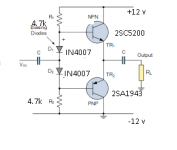
Do not use the schematic on the left. It will go into thermal runaway and destroy itself.
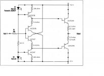
The schematic on the right looks correct. Note the supply voltages.
It is designed to Buffer a low level output voltage. It is not intended as a power Buffer for 4ohms speakers.
Read Andrea Ciuffoli
the Power Folllower
The schematic on the right looks correct. Note the supply voltages.
It is designed to Buffer a low level output voltage. It is not intended as a power Buffer for 4ohms speakers.
Read Andrea Ciuffoli
the Power Folllower
Your choice of output semiconductors have a typical gain of 60, so your poor little BC557/447 will be beyond its limit for any appreciable power output.
Always consider the Hfe of your semiconductors and use that as part of your design. It can be very useful in current limiting.
Both diagrammes are just theoretical so not practical to build as they are.
Diagramme 1 needs emitter resistors!
Always consider the Hfe of your semiconductors and use that as part of your design. It can be very useful in current limiting.
Both diagrammes are just theoretical so not practical to build as they are.
Diagramme 1 needs emitter resistors!
i went threw the circuit The Power follower by Andrea Ciuffoli. but the schematic discussed there are implemented by mosfets. i want to use power transisters. thank you for your openionDo not use the schematic on the left. It will go into thermal runaway and destroy itself.
The schematic on the right looks correct. Note the supply voltages.
It is designed to Buffer a low level output voltage. It is not intended as a power Buffer for 4ohms speakers.
Read Andrea Ciuffoli
the Power Folllower
maximum current possible threw each power transister collector for +-12v supply is 3 A due to 4 ohm load. current gain of 60 means a base current of about 50 ma which is well within range of bc547/557.Your choice of output semiconductors have a typical gain of 60, so your poor little BC557/447 will be beyond its limit for any appreciable power output.
Always consider the Hfe of your semiconductors and use that as part of your design. It can be very useful in current limiting.
Both diagrammes are just theoretical so not practical to build as they are.
Diagramme 1 needs emitter resistors!
its output power is only 20 watt. i am already using this for voltage gain driver and want to increase output impedence of this circuit by using output buffer. i want to use two buffers in bridged mode .
thanks for your suggestion
12v dissipated at .05 amp is 600 milliwatt, very close to 25 deg C power rating of TO92 transistors. You'd be better for drivers with 1 W rated tall TO92 transistors or more commonly TO126 transistors like BC139/140.
Rather than bridging two circuits with two pairs of drivers and hoping for similar gains (ha) use 4 output transistors, two each in parallel and up the driver current with a single pair of TO126 or TO220 driver transistors. I use a heat sink on them, TIP41c/42c in my latest build. No suffix is required for 12 v. You can go down to 33 ohm current limiter
resistors on the drivers with TO220. Current sharing is promoted with 0.5 ohm emitter resistors on the output transistors. Below that you need to do matching of gain and or Vcesat.
If you move your BC557 over to provide input and VAS transistor, you have Kurozz first amp, which has feedback and would sound a lot better. Search for it, he was using 12 v too.
Last edited:
can you send me the schematic of circuit you are talking about. i will be thankful to you for this12v dissipated at .05 amp is 600 milliwatt, very close to 25 deg C power rating of TO92 transistors. You'd be better for drivers with 1 W rated tall TO92 transistors or more commonly TO126 transistors like BC139/140.
Rather than bridging two circuits with two pairs of drivers and hoping for similar gains (ha) use 4 output transistors, two each in parallel and up the driver current with a single pair of TO126 or TO220 driver transistors. I use a heat sink on them, TIP41c/42c in my latest build. No suffix is required for 12 v. You can go down to 33 ohm current limiter
resistors on the drivers with TO220. Current sharing is promoted with 0.5 ohm emitter resistors on the output transistors. Below that you need to do matching of gain and or Vcesat.
If you move your BC557 over to provide input and VAS transistor, you have Kurozz first amp, which has feedback and would sound a lot better. Search for it, he was using 12 v too.
Here is the thread for kurozz first amp. http://www.diyaudio.com/forums/solid-state/297453-tips-first-amp-design-print.html
Latest revised design is post 18, but he put some of andrewt's suggestions in his PCB artwork which is later.
Just substitute 2sc5200/2sa1943 for the TIP31/32 kurozz used. BC547 you have and BC546 he used have similar power ratings, but make sure you get the pnp-npn polarities right. datasheets from datasheetcatalog.com will have the corresponding opposite polarity numbers on them. I use On Semi numbers since I live in the US, I don't memorize the phillips numbers. Phillips is out of the TO92 transistor business anyway, as far as I can tell. The fairchild imitations of BC/BD numbers we can buy have a lot of the specs dropped off.
Last edited:
- Status
- Not open for further replies.
- Home
- Amplifiers
- Solid State
- high power output stage buffer driver for audio amplifier