150W Constant Current Load ( 60V 10A ) - Battery Capacity Tester
Features:
- 60V 10A (derated above 20V)
- 150W maximum power dissipation
- temperature controlled fan
- overtemperature shutdown
- auto/manual adjustment of voltage/current
- capacity counter
- undervoltage protection (load disconnect)
Got this from an Ebay seller at around 25€, also available on aliexpress and others.
Video: https://www.youtube.com/watch?v=6iiBt6EHeSk
Thank you!
I was interest in one and you show just what a needed to know. I meam the minimum adjustable current.
Cheers
Ronaldo
I was interest in one and you show just what a needed to know. I meam the minimum adjustable current.
Cheers
Ronaldo
If you only need current in the milliampere range, a 1-999mA current load might better with better resolution and accuracy.
No, I need 150W power range, so it best suit my needs, but it is interesting to have a low range to use sometime.
Do you already remove fan to see power electronics?
I could see a piece of manganin wire, I suppose it is the current sense.
Regards
Ronaldo
Do you already remove fan to see power electronics?
I could see a piece of manganin wire, I suppose it is the current sense.
Regards
Ronaldo
Haven't removed the heatsink yet. They mounted the NTC temp sensor in the hole of the TO-263 package. 🙂
It's a pretty well made unit.
It's a pretty well made unit.
Fake Units around
I ordered my unit and it was TOTALLY FAKE.
No precision in voltage and current measurements,
Big error in time measures so Ah value is totally wrong;
Over temperature protection activated with 130W continuous;
No resolution in low current range and
The worse it put my power supply in short circuit in pulses. It makes my laboratory power supply to lost the calibration.
It will cost me around US$200 to repair and calibrate my BK Precision 9130 power supply.
So, who is interested on it must take care of the real and fake ones.
Last edited:
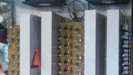
I make recently 800A battery test load. and made 40A in the past.
irfp 260 is better at low cost, it has better wattage. and you can dissipate your heat to ceramic heater instead of all at mosfet.
use white copper manganese, instead of yellow one. and make sure you have it at least with op07 as sensing and feedback.
and isolate the power supply.
irfp 260 is better at low cost, it has better wattage. and you can dissipate your heat to ceramic heater instead of all at mosfet.
use white copper manganese, instead of yellow one. and make sure you have it at least with op07 as sensing and feedback.
and isolate the power supply.
Last edited:
I ordered my unit and it was TOTALLY FAKE.
So it uses PWM to operate the pass FET in switched mode, rather than in a linear mode as a controllable resistance.
That has obvious advantages for the pass FET, and would be somewhat acceptable for battery discharge work if the pass FET had a range of selectable series power resistors to present a known pulsed current level for a particular battery terminal voltage.
Not so good for comparing a battery's rated capacity, unless the tester had the FET on continuously, and even then the test would not be pedantically a constant-current or constant-power discharge.
The design appears to be somewhat similar to a common car battery tester, where a heavy discharge is applied, and the terminal voltage sag with time indicates the 'health' of the battery to perform future starter motor cranks.
It really uses Power MOSFET as power element.
It was operated in linear mode controled by two 18bits DAC and one LM358 as linear control element.
In my point of view is not correct use PWM as discharging or testing load. The pulses can make a power supply instable and no one can predict what happens in chemical of batteries. Maybe good as it is used in desulfators.
Caming bach to my FAKE LOAD, it gives short pulses in protection state. Those pulses was uncontroled and unspected. It damaged my power supply calibration. As those pulses are non controlled it can create serious acidents with batteries.
Order it of course must be avoided as it can be expensive.
Last edited:
Caming bach to my FAKE LOAD, it gives short pulses in protection state. Those pulses was uncontroled and unspected. It damaged my power supply calibration. As those pulses are non controlled it can create serious acidents with batteriey
because it has current sensing for feedback. single stage mosfet will need more time to open from short at starting or at zero current. normally with the feedback sense 0. the mosfet will be controlled to gives more current, it mean short.
and it will ok for big battery. your power supply should be protected from overload. good psu normally have it.
why don't you make yourself? its easier than making class h amp.
I'm attached mine. its my 1st version and already without short pulse.
Attachments
because it has current sensing for feedback. single stage mosfet will need more time to open from short at starting or at zero current. normally with the feedback sense 0. the mosfet will be controlled to gives more current, it mean short.
and it will ok for big battery. your power supply should be protected from overload. good psu normally have it.
why don't you make yourself? its easier than making class h amp.
I'm attached mine. its my 1st version and already without short pulse.
Share your project with us.
It will be very helpfull to see how you drive your MOSFETs as is difficult to share current between lots of this kind of power devices.
I did electronic load project using bipolar a lot of time ago and I could simulate Constant Current and Constant Resistence with over power protection. Old project old technology.
Recently I used power MOSFET in a microcontroled test device for wall wart power supplies.
Both projects was done in industrial enviroment as I am a test engineer.
Maybe I share some schematics but a good reference is the old HP 6060B Electronic load. You can find service manual in keysight site.
By the way, I use to order this new device to learn new technologies, components and topologies. A low cost unit is very usefull to experiences, but for profissional use I have a BK Precision 8500, if I remember well the model.
Last edited:
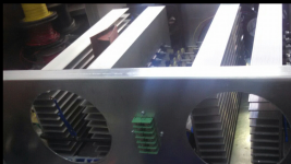
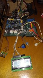
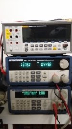
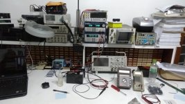
Some Picturs
In attached pictures there is:
- My electronic load testing a 12V power supply at 1,5A;
- Display details (Portuguese Version = Carga Eletronica - Vn = Power supply noise voltage);
- Details of my Power Supply and serious electronic load;
- My laboratory workbench;
This electronic load is rated to 25V 60W 10A maximum. The top right side there is a german shunt resistor. Over the main board there is switched mode power supply to analog and microprocessor and relay board to select AC voltage to test device
Attachments

Last edited:
Are you able to identify if a discrete sensor is causing the gross change in controlled current (eg. a thermal switch), or does the gross change likely occur in uP software - assuming there is a uP doing the controlling as you indicate there are 2 DACs (not sure why there are 2?). It seems like you are saying that the loading grossly changes to an effective short circuit under some operating condition - can you describe that further - and is it momentary, or for some period (such as hysteresis based on a temp sensor). Perhaps you can feed that back to the supplier so that others don't get caught.It really uses Power MOSFET as power element.
It was operated in linear mode controled by two 18bits DAC and one LM358 as linear control element.....
Caming bach to my FAKE LOAD, it gives short pulses in protection state. Those pulses was uncontroled and unspected. It damaged my power supply calibration. As those pulses are non controlled it can create serious acidents with batteries.
Decades ago we used a multiplier IC to provide constant power control for battery testing facilities - but the best design was to switch load element using FETs, and only use a few big FETs operating in linear mode to provide the final level of regulation to achieve CV or CC or CP discharge profiles.
One option to consider for a constant current load is Five Fish Audio's electronic load: DIY Electronic Load PCB Kit for Testing Power Supplies - FiveFish Audio. One nice thing is it uses old stock pentium heatsinks and fans, I was able to pick some up on eBay for a few bucks each.
Share your project with us.
It will be very helpfull to see how you drive your MOSFETs as is difficult to share current between lots of this kind of power devices.
.
no its not difficult, at 1st I thought that it will need a driver to drive the mosfet but later when I tested the load it will ok if mosfet working slowly without driver. and added driver won't solve short pulse.
to avoid short pulse, place another mosfet connected in series with the controlled one. with gate volatage of series mosfet set to around half battery voltage with enough capacitor connected to gate and source. this way when there is no battery the series mosfet will have zero vgs and controlled mosfet will have max vgs. when battery present they will still open and won't make short pulse.
I'll try to find my files and post it here. its my past project and replaced with new one. so these files are somewhere not well cared.
as I remember the series mosfet has current limiter. sensed from those 5w ceramic resistor.
Last edited:
trobbins
The design is very similar in original and fake ones. Almost same components with little diference in positions. It uses microntroller. It looks like the control program is terriblelly bad. Nothing works well.
The fail happens when it was in over temperature protection that happened erroneally in normal working range.
I read that the DAC are Microchip 18 Bits with internal voltage reference and I do not invertigate further to know their funcion.
ontoaba
The principle of electronic load is very simple, I agree. The problem arrice when you use more than one MOSFET. MOSFET do not share the same current and one is prone to fail. One solution you can find in HP 6060B. The 8500 BK Precision uses the same idea. Another point is to have little voltage control. My one is going near to 1V of minimum voltage to control current.
Cold you please draw you solution?
Last edited:
- Status
- Not open for further replies.
- Home
- Design & Build
- Equipment & Tools
- 150W Constant Current Load ( 60V 10A ) - Battery Capacity Tester