klevismuka, a smps that works properly and has design details behind it for all parts and operation is a complex beast. Reverse-engineering from just a schematic only helps an experienced designer for the first 5-10% of effort needed imho. An off-line smps requires even more experience and testing capabilities. A higher powered smps requires even more experience and testing capabilities. That's just my view, but may help appreciate why most posters were rather curt, especially when you only proffered a schematic.
SMPS
klevismuka, these supplies are simply not capable of 2-3Kw.
An EER5555 transformer at 70KHz is capable of less than 180 watts. This information comes from the MagInc website.
I repair QSC amplifiers and they mostly use this EER5555 size core and none of them are capable of these kinds of power.
Of course if you raise the switching frequency to say 250KHz you certainly can get the increased power.
Be carefull of driving these IGBTs directly from the IR2110/3 as they have limited current capability, use either totem drivers are dedicated ICs for this.
Nico good for you in asking all to be polite.
Ons Suid-Afrikaners is geneig om beleefd te wees.
Regards
Steve
To drop this project without starting it?
I do not agree with that, granted it would not be easy, granted it will be very expensive, granted it will require loads of work, still it's NOT impossible, still it's not rocket science! If you pay close attention the every detail it should be ok, and even if, god forbid, you fail, you still will have learn much from the experience. The most important thing is safety, your safety, you have to recognize that you work with lethal voltages, and do anything possible to be safe. All the rest falls second to that.
I am sorry if i am in contradiction with the others but i believe that we should encourage people, help them grow, not cut them down.
MOER i am not sure where do you get your info from but an EE55 power transformer is capable of much more than 180W, way, way more, even at less than 70khz as it is the case here.
IR2110 is quite enough to drive those devices in the schematic, i did checked this to be sure, they are ok.
I think first of all i'll draw a pcb and maybe if i cant build myself other member can, more experienced members maybe can build it and see what happens
klevismuka, these supplies are simply not capable of 2-3Kw.
An EER5555 transformer at 70KHz is capable of less than 180 watts. This information comes from the MagInc website.
Steve
No, definitely not.
Even with ETD39 I pull 400Watts @85kHz (LLC-converter)
Please can you guide me to final version(pcb including)?🙂🙂🙂a 500 to 700W will be enough for your needs? go here, take a look, it is well documented and pcb is available : http://www.diyaudio.com/forums/power-supplies/69111-offline-full-bridge-smps-need-help-62.html
it is only 2 rail voltages and you can learn about how to design a good smps.
hope it helps.
I've had to inherit a nearly 1kW HB which used single pair of E65 N87 running at 40/80kHz. It used 3524 with IR2110 driver and APT FETs. It was low voltage, 220A high current output, so a tad different for transformer practicalities.
Any power supply design has to be based on a detailed set of requirements - do you have a need for this power supply?
Any power supply design has to be based on a detailed set of requirements - do you have a need for this power supply?
I've had to inherit a nearly 1kW HB which used single pair of E65 N87 running at 40/80kHz. It used 3524 with IR2110 driver and APT FETs. It was low voltage, 220A high current output, so a tad different for transformer practicalities.
Any power supply design has to be based on a detailed set of requirements - do you have a need for this power supply?
Just want to build to prove how far can i get. I have mentioned earlier that i can simply build a 200-300-1000w smps, but wasn't so much challenging like this project. But also i'm in dilema should i go further or this is to much for me and just find a pcb online, build that and thats all
Hello Kievismuka, when I first saw that schematic I was astonished by the quantity of discrete components, to me it's not a clean design, looks like lots of workarounds, as someone else mentioned the IRS2110 isn't really suitable for driving IGBT's either.
To adopt someone else's complex schematic is not a good place to start even for an experienced practitioner. I would suggest you find a clean design even if it doesn't meet your power requirements to gain experience with, find out how to test and debug safely before moving on to higher power levels. I don't know how much experience you have of transformer and pcb construction for high voltages but you should ensure you understand creepage and clearance requirements first, for example how do you intend to meet the 4mm requirement within the transformer, are you aware of it ?
I should also add at the power level you are considering PFC is useful and this design you have doesn't have it, must be very old!
Good luck 🙂
Last edited:
...IRS2110 isn't really suitable for driving IGBT's either...
I am not sure as to why do people rush to make uninformed statements but it happens all so often...
At the first glance i also believed that IR2110 could be unsuitable for the power devices, but i had a second look at it, and at the IGBT's detailed specs, and i found that they are quite suitable devices, low capacitance, low charges, the +/-2A of peak current from the driver would have no problem driving them. Check them, and you will see.
I think first of all i'll draw a pcb and maybe if i cant build myself other member can, more experienced members maybe can build it and see what happens
In my country there is a saying quite suitable for the way this topic is going, but i am not sure there is a suitable translation thus i will not even try it, the idea is that there are many roads suggested, many views and opinions, some quite opposed to each other, it is hard for someone inexperienced to get too much help from it...
What i do suggest is that you do not even try to go to the pcb design part, until you have a good and finished schematic, as it is it could work, but still if it were me, i would first optimize it as much as i can, make as many calculations as i can, even simulate what i can, if i can, only after i am sure that all is ok, i go ahead and design the pcb. My latest audio SMPS creation worked just fine first time, without any prototype testing, i have worked on finishind the schematic for months until i was sure of everything, then the pcb design and when i was satisfied i have placed the boards order on some factory, and the first assembled module, was the first fully functional one... What i wanted to say is that it can be done if you pay enough attention to every detail on the schematic design no matter how small.
All the best.
Hello Kievismuka, when I first saw that schematic I was astonished by the quantity of discrete components, to me it's not a clean design, looks like lots of workarounds, as someone else mentioned the IRS2110 isn't really suitable for driving IGBT's either.
To adopt someone else's complex schematic is not a good place to start even for an experienced practitioner. I would suggest you find a clean design even if it doesn't meet your power requirements to gain experience with, find out how to test and debug safely before moving on to higher power levels. I don't know how much experience you have of transformer and pcb construction for high voltages but you should ensure you understand creepage and clearance requirements first, for example how do you intend to meet the 4mm requirement within the transformer, are you aware of it ?
I should also add at the power level you are considering PFC is useful and this design you have doesn't have it, must be very old!
Good luck 🙂
Someone has build it and has video on youtube proving it
Attachments
SMPS
Oops sorry mis typed should be 1,800 watts.
The peak gate current of certain IGBTs taxes IR2110/13 chips and always safet to use a driver circuit
Oops sorry mis typed should be 1,800 watts.
The peak gate current of certain IGBTs taxes IR2110/13 chips and always safet to use a driver circuit
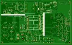
I see, there is no evidence above that.Someone has build it and has video on youtube proving it
Looking at the pcb, the designer obviously ignores any safety requirements like creepage margins between primary and secondary circuits.
Should noobs design for noobs?
I would not say so!
Even with some simple calculation i think EE55 reveals a greater potential than that.Oops sorry mis typed should be 1,800 watts.
The peak gate current of certain IGBTs taxes IR2110/13 chips...
Certain IGBT's yes, not all of them, and not the ones on the schematic shown.
That can be proven by simulation and also calculation.
Hi Everyone,
Most of this project runs directly off the mains, and is therefore inherently dangerous to all near it. The scariest thing you need to think about is that you don't even know what you don't know. Going for such a high power design right out of the gate is ill advised.
It has been suggested earlier that klevismuka should work on a more simple and lower power design that does incorporate the safety features demanded of a line direct powered project. The very act of testing this with a meter (or troubleshooting) exposes the constructor (that would be you, klevismuka) to deadly voltage potentials. Everything looks easy to the untrained.
Should you build one? Sure, why not? But only after some serious study of electrical safety!
Should you build this one? No, I don't think you should. I think that you should take a minute and set aside your pride and carefully consider all the dangers this option presents. Something with less power will stand more chances of success, and from that you will learn. Not from a high powered example that you have shown here. Not for a starting project.
Now for the tough question that we all face when designing something. Just what are you going to use it for when you're done? An extremely high power amplifier isn't a walk in the park to design and build either. This power supply has no practical use even if constructed successfully - not to you at this point in your life anyway. Maybe later when you have more experience and test equipment. For certain, you need an oscilloscope, isolation transformer and some good meters. Then there is that huge isolation transformer you need to run that project on. An isolation transformer is the one thing standing between you and an early grave. No working on this stuff barefoot either!
-Chris
Thank you very much sir, maybe i will go with a 300w. And after build this one
Last edited by a moderator:
Take look at some broken Computer Desktop supplies they have some construction ideas that might be of some help too. You might get some ideas there.
Hi klevismuka,
I think you will be much happier this way. Besides, that computer power supply that was just suggested might have most of the expensive parts you need to build one.
One request, and I am serious about this. Please buy (and use) a 1:1 isolation transformer. It will make your life easier for your entire electronic future and save your skin more than once. I use one on my bench and have for many years. I don't like getting zapped or having employees (trained ones) blow up my ground referenced oscilloscopes. Even old folks like us make mistakes, and the higher the energy levels are, the more deadly the mistakes can be.
Best, Chris
If the ATX psu's are cheap ones, then they would do more harm than good if studied.
Only serious ones can give serious ideas, and they are expensive.
Only serious ones can give serious ideas, and they are expensive.
- Status
- Not open for further replies.
- Home
- Amplifiers
- Power Supplies
- 2KW-3KW Audio SMPS