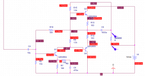
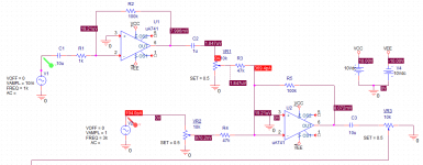
I designed the experimental audio mixer and amplifier with 2 inputs(condensor mic, line) and a 8ohm speaker output. I simulated using pspice.
I'm wondering if it really works using attatched circuit. My circuit have 2 parts :voltage amplifier(op amp) & current amplifier(bjt).
I have 2 current amplifiers and don't know which one is better.
Please let me know the problems on my circuits.
In simulation, the output watt is too smalll.
I'm wondering if it really works using attatched circuit. My circuit have 2 parts :voltage amplifier(op amp) & current amplifier(bjt).
I have 2 current amplifiers and don't know which one is better.
Please let me know the problems on my circuits.
In simulation, the output watt is too smalll.
Attachments

Last edited:
The power will be around 1W more or less, with this 10V supply.
The circuit has been classic many decades ago, its main drawback is the class A driver collector's current flowing through the speaker's coil:
1) This maintain the coil out of magnetic centre,
2) when load is removed before turning on, a powerful pop will sound when coupling it, as the output stage is unbiased.
There are many better solutions. Do you want discrete or chip solutions?
2n3904 3906 as output transistors, the only thing the amp will drive is a crystal earpiece, not an 8 ohm speaker. No current capability, no heat sink.
Cheap to build, try it with TIP41/42 or something as output transistors and put heat sinks on them. Window frame aluminum will do.
You want something more worked out, look at apex AX6, AX8, bigun TGM8. I don't use the exotic transistors required, see above with C suffix over 30 v rail.
The preamp, 741 are hissy, the sound source had better be talk radio or something. 4558 4556 are about as modern you can go without ceramic rail bypass and feedback bypass cap.
Your project will work and is fine as a classroom design , congratulations, but if you want to actually build and use it, pick a tried and true design.
Output transistors chosen are too weak anyway for anything more than, say, an old transistor radio power amp (say, 200/250 mW).
DC current passing through speaker voice coil isn´t technically perfect, but such a low value will not cause trouble.
Such amps were shown as examples in the late 60´s and a couple pocket radios used similar ones.
Thank you for your kind answer. I'm sorry but I did not fully understand your meaning since I could not speak English well. (heat sink, rail bypass,
My project's goal is to make an audio mixer with 200v to 10v dual supply using class AB power amp.(without using IC chip)
It is not an practical amp, so I just want mixed signal output on speaker with power enough to hear in small room.
Since it is a experimental amp for project, it doesn't need to be practical one.
You guys mean that my power amp doesn't have enough power to drive an speaker? (circuit2 or circuit3?)
Is it currently work or should I modify the transistors used at power amp?
I'm wondering if you could give me a amp circuit that serves my goals.
Last edited:
My project's goal is to make an audio mixer
If you want to mix the L and R channels into mono, just use a series 5k resistor
between each RCA input and the mono amplifier pcb input terminal for a passive mixer,
like this.https://upload.wikimedia.org/wikipedia/en/archive/5/5a/20080926174400!Passive_Mixer.jpg
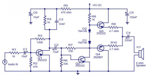
Here are some low power amplifier examples.
http://www.electro-tech-online.com/attachments/simple-simple-amp-png.14695/
http://www.bowdenshobbycircuits.info/amp.gif
Last edited:
If you want to mix the L and R channels into mono, just use a series 5k resistor
between each RCA input and the mono amplifier pcb input terminal.
Thank you for your reply. I have some questions.
I commonly used mono jack at line input since I didn't split L,R channel in my circuit and I mixed mic, line signals
using op amps simply. Should I add 5k ohm register between op amps? I actually don't know RCA, pcb meaning.
Also I checked the circuits you served, I think these
Circuits are quite simple but simmilar with mine.
Is it possible to drive the 8hom speaker with these
Circuits??
Last edited:
Should I add 5k ohm register between op amps? Is it possible to drive
the 8hom speaker with these
Circuits??
To not harm the op amps, use a 5k resistor after each op amp that you will connect together. https://upload.wikimedia.org/wikipedia/en/5/5a/Passive_Mixer.jpg
Those circuit examples should work, but only for a very small speaker at a low volume,
like in a small transistor radio. The power output will be 100mW or less.
The bowdenshobbycircuits is exactly the same as your amp. 100 mw output maybe. Totally inadequate for anything but a crystal earphone.
If you can't use a search engine, here is the link to page 22 of the Apex AX6 amp with 50W. Retro Amp 50W Single Supply - Page 22 - diyAudio
Page 1 has the board if you can etch. on page 22, I built one point to point.
I would assume you would need at least a single 24 v supply for AX6, although as shown it will work up to 70 VDC single supply. I use TIP41C/24C for driver transistors, TIP41C for VAS, (D44R2 is better) MJ15003 for output transistors. TIP41C's are about $.01 more than a 2n3904, MJ15003 is $5. Use a real heat sink for the output transistors. The input transistor 2n5xxx is available from distributors here. The 2sk transistors shown on the AX6 print are more available from counterfeiters on e-bay than any real stocking distributor (here).
Mixer, do as posted previously.
Hi. First, you say you have a 220 V to 12 V transformer. I'm going to assume it's a dual transformer, so you get 2 x 12 V outputs. Now, being how you say it's 220 to 12, I'm assuming that's 12 V AC. When you rectify this, you will probably end up with 18 V DC. So this means you have + and - 18 V DC (or 36 V in total):
I would regulate that down to +- 12 Vdc.
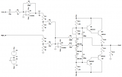
Then, I see that your mixer part with the op amps is already fine for an amplifier - all you need is an output stage. Why not just couple the mixer directly to a class AB stage? You don't need a full discrete amplifier to power the speaker. Have a look at the schematic I attached - I've taken your op amp circuit (ignore the op amps I used) and just fed that into a class AB, then I've taken feedback from the output of the class AB rather than the output of the op amp. This should do about 4 W or so.
Just note - R16 is a 100 ohm trimmer, and must be set to 0 ohms. Then power on and set the bias current to something like 10 or 15 mA.
An externally hosted image should be here but it was not working when we last tested it.
I would regulate that down to +- 12 Vdc.
Then, I see that your mixer part with the op amps is already fine for an amplifier - all you need is an output stage. Why not just couple the mixer directly to a class AB stage? You don't need a full discrete amplifier to power the speaker. Have a look at the schematic I attached - I've taken your op amp circuit (ignore the op amps I used) and just fed that into a class AB, then I've taken feedback from the output of the class AB rather than the output of the op amp. This should do about 4 W or so.
Just note - R16 is a 100 ohm trimmer, and must be set to 0 ohms. Then power on and set the bias current to something like 10 or 15 mA.
Attachments
Thank you for your advice.
First, since I only have 10v regulator chips, +-10V is the maximum
power I can supply. (This is one of my goal.) And I have two 8hom speakers with 0.5W,2W.
Since this experiment is just intended to observe the synthesis of signals, the volume of the output is sufficient to determine the composite signal.
Actually, it is hard to buy the new transistors you used(TIP00)
since it takes a week to import directly from abroad.
To sum up, I kwow it is difficult but hope to meet the following conditions.
- maximum supply : 10V
- BJT can be used : 2n3904,2n3906, C1815, A1015
- class AB, opamp : ua741, lm741
- the minimum output volume sufficient to hear the mixed test signals
within 1m. it doesn't need to be loud.
Actually I can use my first circuit, but I'm afraid it would not work at all.
Sorry for my bad design condition. Your advices are so helpful.
Last edited:
Your circuit post 10 will work but same extreme low power problem as e everything else. Regulating down to 5v is counter productive, you need all the voltage you can get. Running open no regulator on the 12 vac transformer will get you 15 v peak anyway.
These no-feedback three transistor designs will sound like ****. 6 transistors is about the minimum get decent sound.
I see maybe a korean flag? I can't make the buttons work on farnell.com Korea website, but look for semiconductors, bipolar transistors, single bipolar transistors, six to forty watt. See what they have in stock. There should be somthing available in TO220 package or TO126 package for about $.40 each. Heat sinks at 15 v can be cut up window frame sheet with holes drilled in. use heat sink compound if you can get some (grease with beryllium in it) which is poisonous, don't touch eyes mouth or nose after using compound until washing.
To scale up a 5 v design to 15 v you calculate the resistors on the first stage to make the idle current about the same as it was for 5 v.
If you have to use TO92 packages (2n3904/3906 2n2222/2907), parallel two or three of them on the output to get a little more current. 1 ohm emitter resistors will make them share current.
Last edited:
Thank you for your advice.
First, since I only have 10v regulator chips, +-10V is the maximum
power I can supply. (This is one of my goal.) And I have two 8hom speakers with 0.5W,2W.
Since this experiment is just intended to observe the synthesis of signals, the volume of the output is sufficient to determine the composite signal.
Actually, it is hard to buy the new transistors you used(TIP00)
since it takes a week to import directly from abroad.
To sum up, I kwow it is difficult but hope to meet the following conditions.
- maximum supply : 10V
- BJT can be used : 2n3904,2n3906, C1815, A1015
- class AB, opamp : ua741, lm741
- the minimum output volume sufficient to hear the mixed test signals
within 1m. it doesn't need to be loud.
Actually I can use my first circuit, but I'm afraid it would not work at all.
Sorry for my bad design condition. Your advices are so helpful.
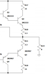
Don't worry about my transistors and op amps. If you don't have access to a power transistor (even if only NPN), then you can only end up with a low-power amplifier. You could put many 2N2222's (or 2N2907's for the other side) in parallel, but you still need to consider what power they can dissipate.
Use 10 V regulators then. The circuit will remain unchanged.
If you use a 2N2222 rather than a TIP41 and a 2N2907 rather than a TIP42, then make the 1 ohm resistors 3.3 ohms, and put 15 ohm resistors in series with the collector of Q2 and Q3. Also set your bias current to no more than 5 mA.
You can get about 800 mW out of such a thing, which isn't bad at all!
But definitely try to connect some sort of heatsink to the output transistors.
This for TO-18:


Or this for TO-92:
An externally hosted image should be here but it was not working when we last tested it.
I've attached the modified output stage I'm talking about.
Attachments
@Mrcloc
@Mrcloc
Thank you. Then what is the trimmer's function?
Is it different from potentiometer?(variable R)
I didn't understand the meaning of "set to 0" .
@Mrcloc
Thank you. Then what is the trimmer's function?
Is it different from potentiometer?(variable R)
I didn't understand the meaning of "set to 0" .
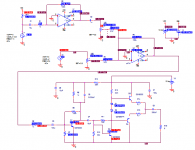
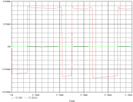
As Indianajo said, I simulated this temporary circuit.
I modified some component values to meet the prior bias condition(5v)
I measured voltage and current on input and output of each mixer,
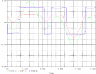
amplifier. Then the output signal had distortion like square wave.
what is this? And the output wattage (dc?) was 180~200mW.
Is this meaningful value?
I modified some component values to meet the prior bias condition(5v)
I measured voltage and current on input and output of each mixer,
amplifier. Then the output signal had distortion like square wave.
what is this? And the output wattage (dc?) was 180~200mW.
Is this meaningful value?
Attachments
Is the waveform going into C3 also a square wave? then turn down the volume on the op amps. The square wave out is called clipping, caused by too much gain.
If the input of C3 is a sine wave but the output of C8 is a square wave, decrease r13 to cut the gain of Q1.
Do you have metal can TO18 2n2222/2n2907 or plastic TO92 version (which means they are not real- real plastic versions are called PN2222/PN2907). The metal can ones can use a heat sink to increase power. Metal can ones haven't been for sale here since the early 1980's, except surplus houses and military suppliers.
C8 of 220 uf won't pass much bass. 2200 uf is more usual. Of course if the speaker is 100 ohms up or a piezoelectric earphone (crystal earphone) then 220 uf output cap is fine.
180 mw out may not melt the output transistors.
I'm not going to download the datasheet on old obsolete transistors I couldn't buy here. You may download datasheets from datasheetcatalog.com or alldata.com . What is power rating of C1815 A1015? Bigger than PN2222/2907? Is thermal resistance to ambient lower than PN2222/PN2907? Then use those for output transistors, with heat sinks.
Again unregulated power to the power amp stage gives more power. 15V instead of 10. You may need to increase the value of the collector resistor of the input transistor Q1 to prevent overheating.
Last edited:
Hi indianajo. The 2N2222's are rated 500 mW minimum. Some datasheets rate them at 800 mW. Those C1815 and A1015 are 150 mW. The most ideal transistors for the output from this selection is the 2N2222/2907's.
radioproject, it's pointless to go the route of lower supply, and single-supply.
The trimmer is a potentiometer, but they usually don't have good specifications on the number of times you can turn them. So they're set-and-forget devices generally. Set to 0 means set that potentiometer so that the resistance over it is 0 ohms. Then turn on, and then measure the current in the output, and change that trimmer until you get to between 2 - 5 mA. No more.
Trimmer:

Again, I don't see the point of adding in an amplifier after the op amps if your op amps can already give you full voltage output swing. Just buffer their output so that you can load with 8 ohms. Buffering means adding a power output stage - this is the circuit I posted. I honestly don't see any better way of doing this than what I posted, provided you only have these transistors. It will get to about 800 mW, which is a heck of a lot more than your alternative theoretical 150 mW. You say this is for instruments, so where are you going to get headroom from when using a microphone? I mean, there's nothing wrong with a 1 W amplifier (or 0.8 W in this case) when powering a 2 W speaker, or even a large 100 dB speaker. But your average power with a microphone is very much less than the maximum power because of the big transients inherent to the raw signal of a microphone. Same with any analogue instrument, like a guitar. 150 mW on 8 ohms is an output of 1.55 V. 800 mW is an output of 3.6 V. That's more than twice the headroom.
radioproject, it's pointless to go the route of lower supply, and single-supply.
The trimmer is a potentiometer, but they usually don't have good specifications on the number of times you can turn them. So they're set-and-forget devices generally. Set to 0 means set that potentiometer so that the resistance over it is 0 ohms. Then turn on, and then measure the current in the output, and change that trimmer until you get to between 2 - 5 mA. No more.
Trimmer:
Again, I don't see the point of adding in an amplifier after the op amps if your op amps can already give you full voltage output swing. Just buffer their output so that you can load with 8 ohms. Buffering means adding a power output stage - this is the circuit I posted. I honestly don't see any better way of doing this than what I posted, provided you only have these transistors. It will get to about 800 mW, which is a heck of a lot more than your alternative theoretical 150 mW. You say this is for instruments, so where are you going to get headroom from when using a microphone? I mean, there's nothing wrong with a 1 W amplifier (or 0.8 W in this case) when powering a 2 W speaker, or even a large 100 dB speaker. But your average power with a microphone is very much less than the maximum power because of the big transients inherent to the raw signal of a microphone. Same with any analogue instrument, like a guitar. 150 mW on 8 ohms is an output of 1.55 V. 800 mW is an output of 3.6 V. That's more than twice the headroom.
Last edited:
What is your main goal?
* Test a synthesizer?
Then forget these obsolete poor performing discrete designs and use a chipamp which will work 100 times better and be easier to build.
* build "an" amplifier, no matter how poor, just for fun?
Then build any of those you posted or the examples you linked to .... just be happy with them "working", preferrably driving a 100 ohm resistor, not enough current capability for an 8 ohms speaker.
You can´t realistically achieve both goals at the same time.
Besides, I am very skeptic that you can find "nothing else but 100mA TO92 diodes" or "10V regulators" at any Korean supplier.
Also quite skeptic about your "0.5W and 2W" speakers.
Just in case, you aren´t realflow100 by any chance?
- Status
- Not open for further replies.
- Home
- Live Sound
- Instruments and Amps
- problem with audio amp circuit design