Note 1 of 2: The Right Way to Do It
.
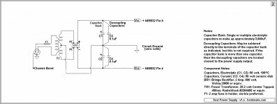
Let me direct your attention to this lovely li'l dual power supply. There's one transformer, one bridge rectifier, and four capacitors, a total of six components. So OK, so the capacitor bank will probably be made up of more than two capacitors, same principle.
This completely ordinary power supply, with an output of about +/-15 volts, will power any DC circuit up to the transformer's load rating. At $8 for the transformer (currently on sale for $6), it costs about as much as a wall wart, not including a housing. It might not be unfair to call its construction near-trivial, hinthint.
.
.
Let me direct your attention to this lovely li'l dual power supply. There's one transformer, one bridge rectifier, and four capacitors, a total of six components. So OK, so the capacitor bank will probably be made up of more than two capacitors, same principle.
This completely ordinary power supply, with an output of about +/-15 volts, will power any DC circuit up to the transformer's load rating. At $8 for the transformer (currently on sale for $6), it costs about as much as a wall wart, not including a housing. It might not be unfair to call its construction near-trivial, hinthint.
.
Attachments
Last edited:
Note 2 of 2: The Wrong Way to Do It
.
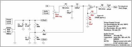
Very much not trivial is running an op amp on a single (as opposed to dual) power supply. A lot of people make it sound like what's the big deal, but none of those people are known to have engineering degrees.
Still, you gotta do what you gotta do, so herewith is presented as seen. The audio circuit is the same as the one in post #5 except for the changes called out in red. The reader is advised, urged, and implored to compare this circuit with the power supply circuit offered above, thereby deciding which is less complicated and less trouble to build.
.
.
Very much not trivial is running an op amp on a single (as opposed to dual) power supply. A lot of people make it sound like what's the big deal, but none of those people are known to have engineering degrees.
Still, you gotta do what you gotta do, so herewith is presented as seen. The audio circuit is the same as the one in post #5 except for the changes called out in red. The reader is advised, urged, and implored to compare this circuit with the power supply circuit offered above, thereby deciding which is less complicated and less trouble to build.
.
Attachments
Last edited:
I have a non-inverting gain stage PCB that might work for you. It includes on board dual rail regulated power supply and is designed to use the LME47920 op-amp. More info on performance here:
http://www.diyaudio.com/forums/mini...in-stage-dc-servo-minidsp-10.html#post4142547
The gain stage board layout has two identical two-channel sections, for a total of four channels. If you need only stereo, just populate one half of it. Gain is determined by one pair of resistors per channel. The circuit is DC coupled with input and feedback RF filtering.
You can implement this after your passive volume control and still use that for volume control.
PM me if you are interested.
Last edited:
Now contradicting everything I've said above, there's not universal agreement about using bypass caps, some consider them of no value.
There IS universal agreement, on all of the manufacturers' data sheets.
1) where does the negative from the power supply (wall wart) hook up to the circuit?
This is a perfectly good question.
Don't get confused by "ground" because it's really just a place in the circuit that other circuit voltages are compared to.
Often it is called "common" instead of ground, although the common can indeed be connected to an actual earth ground,
like a copper pipe in the earth.
If there is only one voltage used in the circuit, let's say that it is positive, then the + wall wart goes to that point,
and then the - wall wart goes to the "ground" or circuit common.
If there are TWO voltages used in the circuit, usually one is + (positive) and one is - (negative), then you need TWO wall warts.
For the positive voltage, one wall wart is connected as above.
For the negative voltage, the + of the other wall wart goes to GROUND, and the - of that wall wart goes to the - voltage circuit connection .
Should this work well?
Yes, but it's very expensive. Consider this one, mine works very well. There is 10k-250k available.
DACT Type 21 Stepped Attenuator Potentiometer 100K * D shape shaft * for Pre/Amp | eBay
rayma -
I already have the Goldpoint. However, I need only a fixed gain stage, so is a pot necessary?
I already have the Goldpoint. However, I need only a fixed gain stage, so is a pot necessary?
I already have the Goldpoint. However, I need only a fixed gain stage, so is a pot necessary?
If you don't need attenuation or variable gain, then it would be a waste of that expensive control.
The best pot is no pot, anyway.
That's exactly what I wanted I to hear!
Sometimes a mute switch to ground is handy. So, what circuit are you going to use?
The one in this thread. I have all I need for it.
Ok, good luck.
- Status
- Not open for further replies.
- Home
- Source & Line
- Analog Line Level
- Looking for a Cheap, simple Opamp gain stage