Help with BHL deluxe phono - SOLVED
After years on not doing much DIY, I thought I'd have a go at the deluxe phono stage.
After completing the build I've started to test with a meter before connecting to an amp or turntable.
I have inconsistencies between the two channels which I'm struggling to resolve;
I'm using a 19v laptop power supply to test with, and measure voltages at varying stages through the circuit.
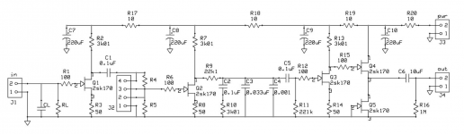
I get a discrepancy at R7 (3K01) / Q2 (2SK170GR), on one channel I get around 9V whilst the other I get 19V, I've checked resistors and changed the JFET. After changing the JFET I got 9V on both before it reverted back to 19V.
Could anyone share any advice ?
Thanks
UPDATE 8/5
Must have been a long day yesterday, on checking again this morning I spotted a dry joint on the resistor connected to the drain on the JFET.
All now works OK albeit with a lash up rig. Time now to wire it up properly into a case.
After years on not doing much DIY, I thought I'd have a go at the deluxe phono stage.
After completing the build I've started to test with a meter before connecting to an amp or turntable.
I have inconsistencies between the two channels which I'm struggling to resolve;
I'm using a 19v laptop power supply to test with, and measure voltages at varying stages through the circuit.
I get a discrepancy at R7 (3K01) / Q2 (2SK170GR), on one channel I get around 9V whilst the other I get 19V, I've checked resistors and changed the JFET. After changing the JFET I got 9V on both before it reverted back to 19V.
Could anyone share any advice ?
Thanks
UPDATE 8/5
Must have been a long day yesterday, on checking again this morning I spotted a dry joint on the resistor connected to the drain on the JFET.
All now works OK albeit with a lash up rig. Time now to wire it up properly into a case.
Last edited:
Can't really advise much without seeing a circuit but one thought... have you applied shorting links to the input for testing ?
I have recently built one also. Curious have you experimented with any different caps other than the supplied PIOs.
I bought the bare board, populated with Takman Carbon resistors, Nichicon KZ Electrolytics. I sourced the PIO capacitors direct from Russia. I'm also using an Alps 'Blue Beauty' 50K pot instead of using resistors in R4/R5 to give me finer control of the gain. For the connections to the RCA sockets I'm using 99.999% 0.5mm sheathed silver wire.
I figured get it working first with the cheap Russian caps (they cost me $18 including delivery) before replacing with something like the Mundorf MCap EVO Silver Gold Oil or Jensen PIO capacitors.
Next step is to put it in a nice case, add some lead acid batteries and a trickle charger then play around with the caps.
One thought has come to mind whilst testing though - before I found the dry joint I was getting around 9V at the output. Had it been connected to the amp it would have done some serious damage. I'm now wondering if a component fails in normal use whether I would get a high voltage again. but more importantly how to shut it down automatically if the output voltage reaches say 3.5V (thinking of a simple circuit with a fuse and 3.6V zenner diode)
Last edited:
I'm now wondering if a component fails in normal use whether I would get a high voltage again.
The safest option is an output blocking capacitor. But, a window comparator can monitor
a filtered version of the output, and trigger an output shorting relay if the offset is excessive.
Include a 1k series resistor in the output before the relay to ground.
That phono preamp has a blocking cap.
If you are measuring any DC (over a few mv) after the cap except for a second or two upon startup then you have problems. And the only problem could be the cap is bad.
I believe you should see half the rail voltage BEFORE the cap, then the cap should eliminate the rest of the DC.
Really, there is no safety mechanism needed...usually the safety mechanism is a cap! If you are really concerned you could insert a relay type DC protection after the cap but it's not really necessary...it's unlikely a Poly cap will go bad.
As for sound quality the important cap is C5, between the stages.
I've had the non-deluxe version of this phono stage (it's pretty much the same thing sans buffer) and have played with the caps quite a bit. It changes the sound, for sure.
Attachments
That phono preamp has a blocking cap. If you are measuring any DC (over a few mv)
after the cap except for a second or two upon startup then you have problems.
And the only problem could be the cap is bad.
He may be measuring the output DC voltage without a bleed resistor to ground.
Is R16 present in the circuit?
OP said bad solder joint at jfet drain...
Could unconnected drain at Q4/Q5 cause DC to bypass cap through R16? I am not sure.
Could unconnected drain at Q4/Q5 cause DC to bypass cap through R16? I am not sure.
Could unconnected drain at Q4/Q5 cause DC to bypass cap through R16?
No way, if the rest of the circuit was properly constructed.
Yes, I would say the bad joint on jet drain and DC on output are two separate issues. The issue of DC on output is curious...Is the OP sure measurement was not taken BEFORE the cap? Because 9V sounds right if measured before the cap.
And the issue of DC on output (if it exists) would scare me if my preamp/amp was not cap coupled.
And the issue of DC on output (if it exists) would scare me if my preamp/amp was not cap coupled.
Thanks for all the suggestions / comments.
Since I've sorted the dry joint its been working well.
I had initially measured the voltage in and out of every component and at the output RCA with the bad joint was giving me around 9V, which led to the concern if things broke in the future and potential damage.
Output is now where I'd expect it to be in the mV's
I'd be interested to hear other peoples experiences of changing capacitors
There is no way to get 9V on the RCA out of that cap coupled circuit unless the cap is shorted...but anyways, here is my impressions of cap changes:
I have the standard BHL phono. I had the Russian PIO caps (dense sounding, perhaps a bit dull) and changed to WIMA's which sounded more balanced but maybe a little unexciting.
Big change was the inter stage coupling cap to polystyrene REL cap, the sound opened up a lot. Then i put a Jantzen Silver on the output which opened up the sound some too.
So I ended up with Wima in the RIAA filter, REL polystyrene coupling and Jantzen Silver for output. I always ran off of alkaline batteries. I tried nicads but they did not seem to sound as good. I also thought it sounded better at 25-26-ish volts than lower voltages.
It is a nice phono stage for cartridges that don't require low capacitance loading.Now I use the Salas folded phono stage which sounds better but is a little more complex (similar topology though). Interestingly, the Salas phono sounds better with shunt regs than batteries.
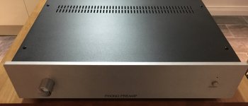
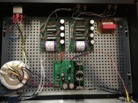
I thought it was about time to post some pictures of my finished project, before I start changing capacitors 🙂.
I ended up making up a power supply from an AMB Labs pcb and getting a case machined and printed from HiFi2000
I must admit I'm happy with the cosmetic results. 🙂🙂
I ended up making up a power supply from an AMB Labs pcb and getting a case machined and printed from HiFi2000
I must admit I'm happy with the cosmetic results. 🙂🙂
Attachments
- Status
- Not open for further replies.
- Home
- Source & Line
- Analogue Source
- Help with BHL deluxe phono