Member
Joined 2009
Paid Member
I can believe that, as we know poor implementation of feedback circuits can produce some nasties.Many said that the problem is the feedback? May be power supply is not so different with amplifier?
I just noticed that when you changed the Salas design by using a BD140 you broke the design because the Vbe is too low to support the preceding CCS. With a MOSFET this isn't an issue because of the relatively large Vgs.
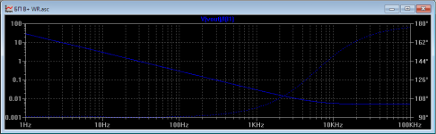
A very correct and subtle question about impedance! In my opinion and some generalization of the available information (namely, from sound applications), it is more important that the impedance is stable from the frequency. An example on the simulation diagram below.Would someone tell my why low output impedance matters? I could imagine 10R with carefully placed decoupling or whatever it is best called would do the same job. Surely the impedance or current use of a circuit is a factor? Is not every ground connection and track throwing it away?
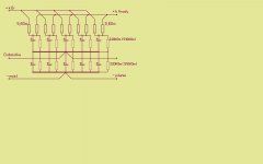
We replace one capacitor C2 - with parallel capacitors connected in series (due to the operating voltage) 10 capacitors, but with additional resistors of nominal 5.6 Ohm. Say: "ruin ESR! Yes! "Low-ESR "is actual in filters of switching power supplies, and in audio the more reasonable value and overall stability from frequency is more reasonable.Also, pay attention to the phase change ...
This approach already works in the "gland" and is checked by "ears".
Attachments
Member
Joined 2009
Paid Member
I just noticed that when you changed the Salas design by using a BD140 you broke the design because the Vbe is too low to support the preceding CCS. With a MOSFET this isn't an issue because of the relatively large Vgs.
did this get answered in post #163-5 or do you think this is still a show stopper ?
(I don't have good device models in Spice for device saturation)
The Vce of Q4 is going to be approximately zero volts. This would be a showstopper for me.
There are things you can do (off the top of my head as I type this):
add an emitter diode to the BD140
add a base diode to the BD140
replace the CCS with a J505 and run it from the +36V supply, perhaps via an RC filter.
use a MOSFET
Use a resistor instead of a CCS
The latter is quite a simple solution...why didn't you do this in the first place?
Member
Joined 2009
Paid Member
I started out with a resistor but was looking for lower Zout. Perhaps a MOSFET is a good idea, they are robust and there are plenty of them available.
You are better off with a resistor and BJT than a MOSFET. Remember the Sumo video? 😛
Nigel asks a very good question: just how low do you need the output Z to be? Zero ohms is not the right answer.
Aside: Other people get into all sorts of trouble by chasing unnecessary goals and end up making bad sounding stuff. I see it all the time and we read about this and that slew rate and output resistance and bandwidth and so on, and more often than not poor audio performance as a result. Having way more of some parameter than you need does not make the sound better; it is the result of bad thinking (mis-attribution). The one that keeps making me grin is the idea that bandwidth >>20kHz is needed. If it is not clutching at straws it is probably marketing.
Last edited:
Member
Joined 2009
Paid Member
Well you sometimes do want bandwidth in excess of 'needs' in order to control phase at the upper end. In feedback amps phase is everything.
How low should Zout be ?
That's the right question for sure but the answer is difficult. Listening tests referred to earlier suggests a subjective element exists, lower Zout correlates with subjectively better performance. I think it's already been pointed out (somewhere) that it's important for Zout to be consistent across the audio frequency range - which in a simple shunt like this one isn't going happen perfectly because stability demands some roll-off in the OLG.
Clearly, there's no point in Zout being any smaller than parasitic impedance down the pcb tracks etc.
The phono +Ve rail has a resistor loaded cathode coupled amplifier. It would be desirable for the power supply rails to have a Z much lower than that resistor. I think I've pegged that resistor to 100R (not 82R) so if I want, say, 80dB of separation then my Zout should be 100R/10,000 = 10mOhm. I'm clutching at straws here but it's one way to look at it.
What's the aversion to FETs - there are some nice FETs these days with decent transconductance (less Sumo)
That's internal bandwidth which feedback forces you to extend as you say.Well you sometimes do want bandwidth in excess of 'needs' in order to control phase at the upper end. In feedback amps phase is everything.
Have a look for the best MOSFET you can find and the best BJT. BD140s are ancient. Then we can compare. How much idle current are you planning for it?What's the aversion to FETs - there are some nice FETs these days with decent transconductance (less Sumo)
Ok. 80dB channel separation is a fair basis to decide what's needed. I would need to simulate the PSRR of the NAD circuit.The phono +Ve rail has a resistor loaded cathode coupled amplifier. It would be desirable for the power supply rails to have a Z much lower than that resistor. I think I've pegged that resistor to 100R (not 82R) so if I want, say, 80dB of separation then my Zout should be 100R/10,000 = 10mOhm. I'm clutching at straws here but it's one way to look at it.
Ok. 80dB channel separation is a fair basis to decide what's needed. I would need to simulate the PSRR of the NAD circuit.
The .asc is attached in post 53.
Member
Joined 2009
Paid Member
Assume that the phono has virtually no PSRR (i.e. 10dB at most) and you get a sense of the challenge.
fyi - Channel separation will be much better than implied by Zout of the shunt regulator - the pcb I'm calling 'Board#1' is mono. The other channel gets a complete copy, with it's own shunt regulator. There is no theoretical issue with channel separation unless I mess up the implementation such as the grounding scheme. I want to keep the power supply from impacting the sonics which is a risk if the signal current flowing through it develops a voltage that's more than, say, -80dB that of the voltage developed across the previously referenced resistor which is the signal voltage to the phono output stage. This may not be a valid way of thinking about it, I was trying to answer the question 'what Zout do I need' and to be honest I'm not sure the best way to calculate it but this off-the-cuff approach provides some insight I hope. In my own simulations of a complete Board#1 with all circuits active, there is no issue at all - signals flowing through the buffer amp for example simply can't reach into the phono stage via the power rails with any significance. Load impedances are high so currents are small and hence voltages developed across parasitic impedances are tiny. I don't know but I suspect a Zout of 10mOhm is lower than I need.
Brian - for the shunt device what we want is transconductance, this will tell us how well it will control Zout. It matters not that BD140 is ancient, pretty much all bipolar devices have the same transconductance for the same collector current. FETs are usually a poor cousin (not as bad as JFETs or tubes mind) but there have been developments in recent years. Hugh Dean now uses MOSFETs because he finds their transconductance is now 'good enough' (those are my words - he's very careful with parts choices). However, that's in power amps where there's a lot of current flowing. For this shunt regulator I'm looking for ~10mA idle current through the shunt device when the attached circuits are active. Maybe it should be higher, but it won't be 100mA. I haven't looked at candidate FETs yet, maybe I'll only find sumo....
Last edited:
Thanks for that post# mjona. The PSRR of that NAD circuit is atrocious at 20Hz...there isn't any. But if you are independently regulating each channel then you need a new criteria for deciding the shunt Z. Take a look at the stability of your circuit; another way to choose Z.
Transconductance isn't the only consideration. 😎
Transconductance isn't the only consideration. 😎
Member
Joined 2009
Paid Member
Thanks for that post# mjona. The PSRR of that NAD circuit is atrocious at 20Hz...there isn't any. But if you are independently regulating each channel then you need a new criteria for deciding the shunt Z. Take a look at the stability of your circuit; another way to choose Z.
Maybe my simulations are flawed somewhere but I'm not seeing any issue with PSRR for the shunt+phono combination. No need to add complexity. However, my criteria, admittedly a quick-think suggestion, isn't about channel separation. It's about keeping voltage drop from signal currents off the power rails and keeping them inside the amplifier.
Stability does require care and simple capacitance on the rails addresses it easily but of course output impedance increases with frequency but not to an extent that it's no longer attractive.
Attachments
As far as local supply rail decoupling is concerned I see only one on the RIAA stage C3 at 100n and none at all on the buffer board.
If you want to short some supply line rubbish away from sensitive circuit input points - you would install them where there is a short distance between such and the decoupling capacitor. You can use a modern electrolytic for this - said Guido Tent an EMC engineer at Phillips 20 years ago.
If you want to short some supply line rubbish away from sensitive circuit input points - you would install them where there is a short distance between such and the decoupling capacitor. You can use a modern electrolytic for this - said Guido Tent an EMC engineer at Phillips 20 years ago.
In the world of valves there are big issues of how possible is it and Folklaw.
I built an SE valve amp with very low distortion that used tricks of 1960's transistor amps. This was a design for a friend so I got rid of as many transistors as I could at the end as he is a Folklaw type, The MJE350 CCS was great to the driver valve anode. Were it not for a 600V MOSFET as a capacitance multiplier it would have had none. I kept it as the valve people don't hate FET's and it was better than a bipolar doing this difficult job ( A bipolar needs zener protection on start up due to not having the 500V spec it needs ). - 88dB hum reference 1 watt is very good for a SE valve design. However there was an interesting thing of note. The second harmonic distortion was very slightly higher with the FET in place. Even though the MOS FET cap multiplier is as simple a one can have it is interactive with the amplifer. As this amp used maximum 80mA it is not far away from a preamp current. The voltage regulator will do many more things than imagined. As someone said we can use a RC filter after the regulator as a way of cheating the regulator out of it's desire to join the party. On my phono stage I use 27R and 4700 uF and 1uF with 10 nF + to - on the op amps.
I built an SE valve amp with very low distortion that used tricks of 1960's transistor amps. This was a design for a friend so I got rid of as many transistors as I could at the end as he is a Folklaw type, The MJE350 CCS was great to the driver valve anode. Were it not for a 600V MOSFET as a capacitance multiplier it would have had none. I kept it as the valve people don't hate FET's and it was better than a bipolar doing this difficult job ( A bipolar needs zener protection on start up due to not having the 500V spec it needs ). - 88dB hum reference 1 watt is very good for a SE valve design. However there was an interesting thing of note. The second harmonic distortion was very slightly higher with the FET in place. Even though the MOS FET cap multiplier is as simple a one can have it is interactive with the amplifer. As this amp used maximum 80mA it is not far away from a preamp current. The voltage regulator will do many more things than imagined. As someone said we can use a RC filter after the regulator as a way of cheating the regulator out of it's desire to join the party. On my phono stage I use 27R and 4700 uF and 1uF with 10 nF + to - on the op amps.
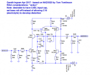
Suggested improvements to NAD phono stage to improve PSRR and stability. Note transistor values. Use a high quality 100uF for C1. I have measured PSRR and frequency domain response. I have not measured noise or THD.
Attachments
Last edited:
I like that. If not wanting the bass roll off a 2u2 or 4u7 could be used. A switch to put the higher values in paralell if unsure how you want to go.
Member
Joined 2009
Paid Member
I've looked at the bass roll-off of the phono amp in LTSpice. I can't see why the heck they used such large capacitors for the input and output coupling, at least with a high impedance buffer after it. One reason might be to reduce the signal voltage across the capacitors by using large values; it is a known method to avoid electrolytic 'distortion'. However, it's quite clear from both simulations and other published phono amp designs that these caps can be smaller. I believe we can use 0.47uF without issue and then you can use film caps for both positions, e.g. metallized polypropylene. The feedback shunt cap has a decent polarizing voltage across it and by using a non-polar electrolytic with very little signal voltage across it the 'capacitor distortion' can be very small. To achieve this it's important to ensure that this electrolytic is not used to establish the bass roll-off frequency. Hence it's better to limit the bass somewhere else such as by using a film cap at the input and limiting it's value so that the bass rolls-off before the feedback shunt cap runs out of steam. I'm looking for bass roll off to start around 20Hz although I have no plans for a sub-sonic filter per se. A 470nF input cap and a 47uF feedback shunt cap are at the design limit for these considerations, I may want to use a larger feedback shunt cap whilst keeping the input cap at 470nF.
Last edited:
" I can't see why the heck they used such large capacitors for the input and output coupling,"
Study both magnitude and phase. You'll find that phase starts to deviate from perfection, much sooner than magnitude does. Look into your heart and decide how many radians (degrees?) of phase deviation you are willing to tolerate. Very few internet pontificators have issued decrees and proclamations about this, so you may be forced to rely on your own engineering good judgement.
Study both magnitude and phase. You'll find that phase starts to deviate from perfection, much sooner than magnitude does. Look into your heart and decide how many radians (degrees?) of phase deviation you are willing to tolerate. Very few internet pontificators have issued decrees and proclamations about this, so you may be forced to rely on your own engineering good judgement.
- Status
- Not open for further replies.
- Home
- Source & Line
- Analog Line Level
- TGMC - a modular control pre-amplifier