There's a case to be made for a PP 300b amp. I'd use a 4P1L to drive the outputs, into a phase splitter interstage. Maybe something like a LL1660S. It would need to be gapped for 25ma.
http://www.lundahl.se/wp-content/uploads/datasheets/1660S.pdf
Then drive that with a 01A Gen 2 stage. Should sound great. I don't need the power, but I'm sure I'll build it one day just to see how it sounds.
In progress 😀. If you call my glacial pace progress...
http://www.diyaudio.com/forums/tubes-valves/299518-pp-300b-project-3-stage.html
I know DHT drivers would likely be superior, but baby steps.
I figure 19-20w class A should be just dandy
Last edited:
Uhhh, well . . . not all recordings are mixed and mastered the same so it's unrealistic to expect them to all have tonal characteristics that match your taste.
The solution is not to redesign the circuit or build an expensive new amp. Just add a studio quality EQ, either graphic or parametric, and adjust as necessary. Simple.
I know most here probably consider this advice as heresy 😱 but you can be absolutely sure that the recording and mastering engineers used exactly the same type of components during the recording, mixing and mastering process. Their EQ choices just don't seem to align with your preferences, that's all.
When a recording engineer doesn't like the tonal balance of a recording, they don't build a new studio, they tweak a few knobs.
Nah, I have done enough diagnostics to know its the amp.
Plus its not like the vocals are only slightly recessed and I am just being picky. Its pretty dramatic.
It would be nice if we had a schematic of your amplifier, including the 350B plate voltage,
self bias voltage (or fixed bias voltage; state which one), plate current, and transformer primary impedance.
It would also be nice if you state what loudspeakers you are using.
Here are a couple of examples of what a triode wired 350B can do.
(Compare that to what a New Old Stock (NOS) 45 can do 2 watts at 5% if the output transformer is very low loss).
Western Electric 350B Triode Wired
250V plate 250V plate
-20V grid -20V grid
50mA 50mA
5000 Ohm load 6000 Ohm load
1.7 Watts 1.5 Watts
5 % THD 6% THD
Start with exactly what you have, and perhaps one of us can get you where you want to be.
I will post something later today. I have changed the circuit so much that I don't have a real schematic to give.
I would actually really like to keep this amp. My friend made it for me and its pretty special to me.
Last edited:
andyjevans,
Nobody seemed to notice:
if I understand what you said: filament self bias for a 2A3 requires the bias resistor to pass the bias current (60mA), And the filament current (2.5A). That is incorrect.
Instead, the 2.5A filament supply has to be Floating, not ground referenced, and has to be connected Only to the filament pins. That is true for a filament supply (AC or DC) when the 2A3 is used in a self biased circuit.
Example:
2A3 Self bias:
A Floating 2.5VDC is applied to the filament pins 1 and pin 4. A 25 Ohm resistor is connected to pin 1 and a 25 Ohm resistor is connected to pin 4. The other ends of the 25 Ohm resistors are connected together and to the top of a 750 Ohm resistor, and the other end of the 750 Ohm resistor is connected to ground. A bypass capacitor is connected across the 750 Ohm resistor. The 750 Ohm resistor only has to pass 60 mA, not 2.5A.
45V/750 Ohms = 60 mA.
Technically, the two 25 Ohm resistors mean that it is 12.5 Ohms from the filament to the top of the 750 Ohm resistor. So it should be 750 - 12.5 = 737.5 Ohms,
but the 750 Ohm resistor is practical and good enough.
For DC filament power, and Fixed Bias, the 750 Ohm and bypass capacitor are not used, and the common ends of the 25 Ohm resistors that are connected to each other are also connected to ground. The -45V 'fixed' bias is applied to the bottom of the 2A3 grid resistor, and the top of the grid resistor is connected to the 2A3 Grid.
You could eliminate the 25 Ohm resistors if you ground one end or the other of the filament supply, but now the bias will be incorrect by 1.25V (1/2 of the 2.5V).
AC filaments normally requires a floating filament supply, and at least the two 25 Ohm resistors, and usually a potentiometer between them, in order to balance out the hum as much as possible.
The center of the potentiometer is connected to the top of the 750 Ohm resistor for self biased circuits, and to ground for fixed bias circuits.
Some of the hum can not be balanced out, because of the electromagnetic effect of the AC in the filament wires, and the attraction of the filaments to the steel plates.
Last edited:
my PP 6B4G amps run out of gas on big orchestra on 93db speakers, though it is a fairly large room.
They get loud enough - but the distortion at top output is too high. It's not bad - just not good enough.
I had no problem pushing 89 db speakers with my 2a3 PP. At full output less than 2.5% THD and no nasty top end etc.
I found that nasty top end is easy to get if your input/driver stage has design issues..... Work on that part and you will likely solve a ton of problems.
andyjevans,
Nobody seemed to notice:
if I understand what you said: filament self bias for a 2A3 requires the bias resistor to pass the bias current (60mA), And the filament current (2.5A). That is incorrect.
Instead, the 2.5A filament supply has to be Floating, not ground referenced, and has to be connected Only to the filament pins. That is true for a filament supply (AC or DC) when the 2A3 is used in a self biased circuit.
Example:
2A3 Self bias:
A Floating 2.5VDC is applied to the filament pins 1 and pin 4. A 25 Ohm resistor is connected to pin 1 and a 25 Ohm resistor is connected to pin 4. The other ends of the 25 Ohm resistors are connected together and to the top of a 750 Ohm resistor, and the other end of the 750 Ohm resistor is connected to ground. A bypass capacitor is connected across the 750 Ohm resistor. The 750 Ohm resistor only has to pass 60 mA, not 2.5A.
45V/750 Ohms = 60 mA.
Technically, the two 25 Ohm resistors mean that it is 12.5 Ohms from the filament to the top of the 750 Ohm resistor. So it should be 750 - 12.5 = 737.5 Ohms,
but the 750 Ohm resistor is practical and good enough.
For DC filament power, and Fixed Bias, the 750 Ohm and bypass capacitor are not used, and the common ends of the 25 Ohm resistors that are connected to each other are also connected to ground. The -45V 'fixed' bias is applied to the bottom of the 2A3 grid resistor, and the top of the grid resistor is connected to the 2A3 Grid.
You could eliminate the 25 Ohm resistors if you ground one end or the other of the filament supply, but now the bias will be incorrect by 1.25V (1/2 of the 2.5V).
AC filaments normally requires a floating filament supply, and at least the two 25 Ohm resistors, and usually a potentiometer between them, in order to balance out the hum as much as possible.
The center of the potentiometer is connected to the top of the 750 Ohm resistor for self biased circuits, and to ground for fixed bias circuits.
Some of the hum can not be balanced out, because of the electromagnetic effect of the AC in the filament wires, and the attraction of the filaments to the steel plates.
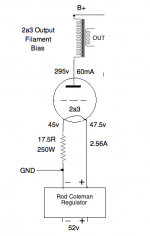
I have used an AC 1.25v - 0 - 1.25V filament transformer to cathode bias 2a3 with good results. The power cathode resistor attaches to the center tap and goes to ground. Its a pretty much idiot proof construction, but if the filament transformer is of the extremely cheap variety you might find the hum bucker approach worth considering.
DC filament bias won't work for 2a3. You will need to do 43.5V at 2.55A... (that will take a HUuuuuge resistor). Fixed bias works though.
Ian
Last edited:
andyjevans,
Nobody seemed to notice:
if I understand what you said: filament self bias for a 2A3 requires the bias resistor to pass the bias current (60mA), And the filament current (2.5A). That is incorrect.
Instead, the 2.5A filament supply has to be Floating, not ground referenced, and has to be connected Only to the filament pins. That is true for a filament supply (AC or DC) when the 2A3 is used in a self biased circuit.
That's not filament bias. This is filament bias.
Attachments
Regarding IDHT->DHT vs DHT->DHT what are we looking for in the measurements that makes DHT->DHT superior?
In a single ended amp there would be no distortion cancellation and there are already suitable low distortion IDHT drivers that are capable of driving a 300B with 6 dB of headroom.
In a single ended amp there would be no distortion cancellation and there are already suitable low distortion IDHT drivers that are capable of driving a 300B with 6 dB of headroom.
Regarding IDHT->DHT vs DHT->DHT what are we looking for in the measurements that makes DHT->DHT superior?
In a single ended amp there would be no distortion cancellation and there are already suitable low distortion IDHT drivers that are capable of driving a 300B with 6 dB of headroom.
I'm sure there are some posts somewhere on this site that talk about measurements of IDHTs and DHTs. They may or may not be of interest to those who choose DHTs simply on the basis of listening to them in various DIY builds. But I'm sure they would be interesting to you if you can find them.
That's not filament bias. This is filament bias.
Yup. it won't work. Show me this amp and I will show you a nice way to heat the living room.
http://www.mouser.com/ProductDetail/Vishay/RH25016R70FJ01/
The power resitor is 11cm long, 5cm high... 7.5cm wide.... Just imagine what you will need to sink the heat! 😀
I did mention the 45 tube in an earlier post in this thread. But that does not mean that I was suggesting using it, but only to compare it to the usual output power of a triode wired 350B (and the distortion will likely also be similar).
You should keep the 350B amp. But you also ought to consider building either a 2A3 or a 300B amp.
I have used 45, 2A3, 6A3, and 300B (many other tubes as well).
My speakers are 87 dB, and fairly easy impedance to drive.
The 2A3 will probably have enough power for your 90 dB speakers, depending on your
speaker impedance versus frequency, room size, type of music you play, and how loud you like to listen.
The impedance versus frequency of the loudspeaker, and the damping factor of the amplifier will largely dictate the frequency response of the system (as the room will too).
And Harmonic Distortion and Intermodulation distortion can also affect the perceived balance of the system. And distortion goes up as the loudspeaker impedance goes down.
Regarding IDHT->DHT vs DHT->DHT what are we looking for in the measurements that makes DHT->DHT superior?
In a single ended amp there would be no distortion cancellation and there are already suitable low distortion IDHT drivers that are capable of driving a 300B with 6 dB of headroom.
You can't cancel distortion. Once distortion is present it won't go away.
However you can always consider some feedback, even in a single ended amplifier. Even in a DHT single ended amplifier...
I've been using triode strapped pentodes with gyrator biased cascoded CCCS's for some time now, but I would not use this to drive the 300b. MOSFET followers do a far better job driving the 300b.
Ian
I had no problem pushing 89 db speakers with my 2a3 PP. At full output less than 2.5% THD and no nasty top end etc.
I found that nasty top end is easy to get if your input/driver stage has design issues..... Work on that part and you will likely solve a ton of problems.
Amperex 5842's transformer coupled, stupid simple really. I don't have the means to measure distortion, but I can hear it at the upper limits of output, not harsh, just loss of definition. AB1 the culprit? Leading edge of soft clipping?
Yeah, I'm nit-picking, they're really very good and have stayed in my system for years, slaying all challengers. But, it gives me the excuse to build another amp.
Nah, I have done enough diagnostics to know its the amp. Plus its not like the vocals are only slightly recessed and I am just being picky. Its pretty dramatic.
Just to clarify then . . . are you saying that the balance between bass and vocal presence does not change with different recordings using the same amp circuit? Instead, they are noticeable on all recordings and are due to changes you've made in the amp circuit - using one configuration you get bass and weak vocals and using a different circuit you get good vocals but weak bass? You haven't mentioned what speakers you're using. I assume you don't want to change them but, perhaps, that should be a consideration.
Either way, I'd still suggest using a studio quality EQ to adjust the sound. It's simple and it will solve the problem.
You seem to indicate that you have been able to get good vocals, just not good bass at the same time. So another approach would be to go back to the amp circuit that gave you good vocals and then add a decent sub, or an active crossover setup, to improve the bass.
The other posters all suggest new amps you could build - at considerable expense - and now, predictably, there is lots of discussion about the complexities of various circuit designs.
Not a single one of them seem to be addressing your main concern which is the balance between bass and vocal presence. There has been absolutely no discussion or explanation of why any of the suggested amp circuits will solve your problem. Yes, they will sound different from your current amp and perhaps they are better amps, but will they solve your problem? If so, how and why?
I believe the suggestions I've made will solve your problem. But maybe you just want to build a new amp and hope for the best.
Yeah... 5842 is not super-duper gain, is it? But the internal resistance is nice. I would try cascoded CCCS load (with gyrator), even if I was transformer coupling... 😉
You might be very surprised.
You might be very surprised.
Just to clarify then . . . are you saying that the balance between bass and vocal presence does not change with different recordings using the same amp circuit? Instead, they are noticeable on all recordings and are due to changes you've made in the amp circuit - using one configuration you get bass and weak vocals and using a different circuit you get good vocals but weak bass? You haven't mentioned what speakers you're using. I assume you don't want to change them but, perhaps, that should be a consideration.
Either way, I'd still suggest using a studio quality EQ to adjust the sound. It's simple and it will solve the problem.
You seem to indicate that you have been able to get good vocals, just not good bass at the same time. So another approach would be to go back to the amp circuit that gave you good vocals and then add a decent sub, or an active crossover setup, to improve the bass.
The other posters all suggest new amps you could build - at considerable expense - and now, predictably, there is lots of discussion about the complexities of various circuit designs.
Not a single one of them seem to be addressing your main concern which is the balance between bass and vocal presence. There has been absolutely no discussion or explanation of why any of the suggested amp circuits will solve your problem. Yes, they will sound different from your current amp and perhaps they are better amps, but will they solve your problem? If so, how and why?
I believe the suggestions I've made will solve your problem. But maybe you just want to build a new amp and hope for the best.
Good point. Maybe its the speakers or the pre-amp. In which case, only an EQ can help.
Or maybe the amp just can't drive the speakers in the first place. Too little damping? He could add some global feedback.... reduce distortion and increase damping factor.
did we ever see a schematic?
I'm sure there are some posts somewhere on this site that talk about measurements of IDHTs and DHTs. They may or may not be of interest to those who choose DHTs simply on the basis of listening to them in various DIY builds. But I'm sure they would be interesting to you if you can find them.
The only IDHT vs DHT (I'll use this for shorthand, since the output is DHT in both cases) measurements I have seen are on Ale's blog and this post, the latter is an excellent read. IMHO they are all similar to well designed IDHT/DHT amps.
Note- for my own use I am building a SET amp to use in an active system from 300 Hz on up in a constant directivity horn with >100 db/w sensitivity so that leaves me with lots of options and I am leaning towards DHT/DHT. But there is no denying the greater reduction in cost (I'm ruling out 4p1L, just personal taste I am not a fan), complexity and size with IDHT.
For a Triode, Triode wired Tetrode, Triode wired Pentode, or Triode wired Beam Power tube:
I believe that that the term "Self Bias" is where the tube and self bias resistor dictate the Cathode current (or Filament to "plate" current), at a fixed "Plate" voltage. Of course as the tube self biases, the "Plate" to Filament or "Plate" to Cathode voltage is reduced by the amount of the bias voltage.
I have not seen RCA, GE, GEC, Western Electric, or other tube manufactures describe
"Self Bias" to mean anything otherwise.
Of course, I mis-spoke when I said "filament self bias". I meant "Self Bias" for a direct filament tube; not filament self voltage.
The 17.5 Ohm resistor is determining bias more according to the filament to filament current than it is by "Plate" current.
2.5A/0.06A = 41.667:1 ratio.
The 2A3 is supposed to have 2.5V across the filament. 2.5A does not always give 2.5V on a 2A3 filament. Some draw more current, some draw less current.
I hope that clears up the issues.
For a Triode, Triode wired Tetrode, Triode wired Pentode, or Triode wired Beam Power tube:
I believe that that the term "Self Bias" is where the tube and self bias resistor dictate the Cathode current (or Filament to "plate" current), at a fixed "Plate" voltage. Of course as the tube self biases, the "Plate" to Filament or "Plate" to Cathode voltage is reduced by the amount of the bias voltage.
I have not seen RCA, GE, GEC, Western Electric, or other tube manufactures describe
"Self Bias" to mean anything otherwise.
Of course, I mis-spoke when I said "filament self bias". I meant "Self Bias" for a direct filament tube; not filament self voltage.
The 17.5 Ohm resistor is determining bias more according to the filament to filament current than it is by "Plate" current.
2.5A/0.06A = 41.667:1 ratio.
The 2A3 is supposed to have 2.5V across the filament. 2.5A does not always give 2.5V on a 2A3 filament. Some draw more current, some draw less current.
I hope that clears up the issues.
"Filament Bias" is a term used by Thomas Mayer and thereafter by the Hi-Fi community. It probably pre-dates Thomas, but he put it on the map for builders of DHT stages. Can't remember the exact year - I think it was around 2009. It is particularly suited to low bias voltage DHTs, mostly smaller tubes but unfortunately not 2a3, 300b and bigger output tubes. The higher bias voltage and filament current make those impractical.
The use of filament bias - which eliminates the cathode bypass cap - became a really good choice when Rod Coleman developed his filament regs and we were able to get very clean DC voltage on the filaments. Since the signal and filament supply both go through the cathode resistor the supply needs to be uber-clean.
Doing diagnostics on your system, would require using another amp, one that Does sound the way you want it to.
The amp that sounds correct on your system needs to be compared to the one that does not.
Then, you should try to determine if it was related to damping factor, harmonic distortion when loaded by the speaker, intermodulation when loaded by the speaker, output power, etc.
A generalization: Triode or triode wired push pull amps can often deal with loudspeakers that have reactive impedances, the distortion caused by the elliptical load is partially cancelled in the class A region of push pull (not so in single ended).
(Don't get me wrong, I like SE and PP).
To see this, a bit of work is required:
Draw both a straight load line, and an elliptical load line on a set of triode curves.
You can see the effect versus a straight load line (resistor).
Then overlay 2 such SE curves that are rotated 180 degrees relative to each other.
You should be able to see how the eclipse is cancelled in the class A region.
Another generalization: For an SE amp, the 2nd harmonic distortion of the driver stage can partially cancel the 2nd harmonic distortion of the output stage. This can work quite well for resistive loads. But it does not work for reactive (elliptical) loads, since the reactive speaker load is only applied to the output stage, and not to the driver stage.
- Status
- Not open for further replies.
- Home
- Amplifiers
- Tubes / Valves
- 2A3 vs 300B Stuck at a fork in the road.