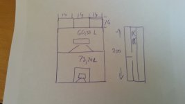
I think you have the wrong orientation of the vents. They are 47x47 in the opening and 107 long.
Uh oh...
Thank you!
Attachments
Last edited:
Now I have the same WinISD as you.
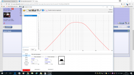
And I have simmed the 9 Wicon line with min. ripple.
73 rear 60 front.
If you use 8 vents 47x47 the opening area is 176,7 cm´2 and the length 13,7cm
And I have simmed the 9 Wicon line with min. ripple.
73 rear 60 front.
If you use 8 vents 47x47 the opening area is 176,7 cm´2 and the length 13,7cm
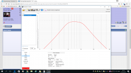
So in order to get more area where the sound comes out, here is another idea.
Back chamber is now in front of the Mivoc´s and front chamber in the back. Vents are behind the cabinet and opens at the top and bottom.
Now the area is 1176 cm´2
Back chamber is now in front of the Mivoc´s and front chamber in the back. Vents are behind the cabinet and opens at the top and bottom.
Now the area is 1176 cm´2
Attachments
The Sd of one woofer is 214cm2 so 81 is about 40% of that. Synergy style ports use 20% of Sd and upwards to keep the velocity under control. 81 per driver is actually quite a lot of vent.Oh - ok I see now. Great.
I think I might have a little reservation concerning this design. The mouth area of the 4 vents is pretty small. Even though WinISD says the velocity is ok small, the combined area of the vents is only 81 sq.cm!
In order to move the air in a big room there has to come a LOT of air out (and in) of these vents. 😕
I think it will work better if you vent each woofer separately otherwise you lose the array effect in the bass frequencies.
I ran another sim for a single mivoc in a synergy style baffle mounted face down with two 40mm holes cut in a 19mm baffle as ports. They can take the rated power without reaching xmax so there is room to EQ the bottom end particularly when you have 9 together.
7 litre rear and 0.6 front which is more realistic for the cone volume with a spacer for the surround. Vent velocity is 18 m/s at 120 Watts.

OK well that is very small then, I only saw one woofer in your drawing probably explains why the sim didn't match 🙄 I don't bother with modelling more than one or two drivers because all that happens is that the output goes up by 3dB in the graph which doesn't always help get a better picture.But 81 was for 9 units!
Simming 9 units saves me the trouble of multiplying the dimensional numbers for the final result
Thanks again for all the time you guys sacrifice! 
Re vent opening: although the CSA has risen significantly, it still seems rather small. But, I can't get a reasonable result from ISD too. So, BP may be out of the game?
Re line array effect: that's what I wondered all the time - when having the low end section in a BP enclosure, where goes the desired line arry effect?
All the best from lousy cold Vienna
Gerald

Going back to this picture:
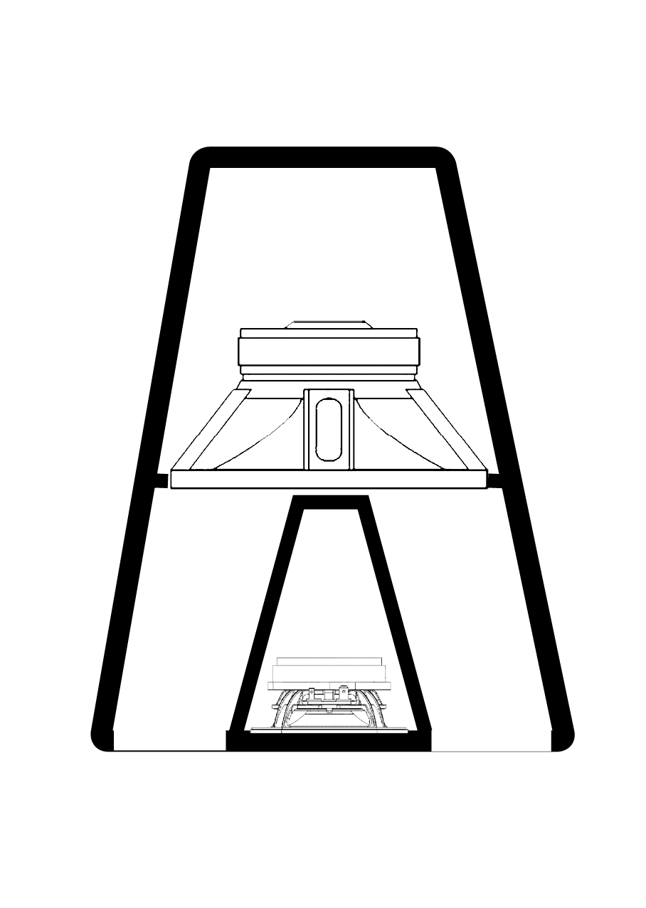
I'm wondering if one of Tom Danley's other ideas might work. His layered combiner. The idea being that the actual sound wave won't start building up until there is room for it to do so. So everything from the woofer baffle to the front would just act as a huge phase plug. Could we use that for bass?
Maybe it isn't even needed, once the bass is time aligned with the TC9 array it will be crossed over low enough to not really see the front chamber shape as a horn. It will probably act similar to the array at that point, wave size being much longer than the surface area will make it omni directional. In other words, it could work as is.
Last edited:
Oh well...
Time aligning subs and FR was one of the goals I stated at post #1. Without, this idea of an array wouldn't work properly.
Time aligning subs and FR was one of the goals I stated at post #1. Without, this idea of an array wouldn't work properly.
Well, simming that is way out of my possibilities 🙁
I'd hope the LF range behaves at least a little bit controlled in regards to vertical dispersion and directivity.
I'd hope the LF range behaves at least a little bit controlled in regards to vertical dispersion and directivity.
the LF range , if it is below 100hz, is omnidirectional anyway
With the speaker dimensions we ar dealing with
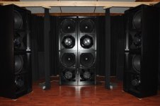
Which is why I still think even the first proposition would work. Kind of makes me think of the CBT line arrays from JBL:
Though our tweeters are way bigger here 😀.
Attachments
Thanks again for all the time you guys sacrifice!
Re vent opening: although the CSA has risen significantly, it still seems rather small. But, I can't get a reasonable result from ISD too. So, BP may be out of the game?
Re line array effect: that's what I wondered all the time - when having the low end section in a BP enclosure, where goes the desired line arry effect?
All the best from lousy cold Vienna
Gerald
What sort of result are you looking to get?
When I mentioned bandpass I didn't mean to put all the drivers in one enclosure and vent through a few holes. I meant each driver in it's enclosure (at least at the front) and separate vents per driver in front of the driver so the array effect is maintained vertically.
Wesayso's drawing is a good example where the white line is across the front you could put a vent hole on each side of the TC9, it can be as big as you want but 2 x 60mm will get you above 20% of the cone area and keep the vent speed down. Put a separator between each driver and the front volume of the horn becomes the chamber volume.
Or you can just leave it open.
The reasons to consider bandpass were shown in the graphs I posted. You can get a useful extension on the low end roll off from a sealed cabinet and still EQ too, you get acoustic filtering of the higher frequencies which reduces distortion.
Go with the 12's if you can.
What sort of result are you looking to get?
Optically, a low footprint column, as unobtrusive as possible - for monument conservation reasons.
Acoustically, one might consider it a FAST line array, my intended FR would be 45Hz to 20kHz. Dispersion should be 30°V x 120°H
When I mentioned bandpass I didn't mean to put all the drivers in one enclosure and vent through a few holes. I meant each driver in it's enclosure (at least at the front) and separate vents per driver in front of the driver so the array effect is maintained vertically.
There I fully misunderstood you, my bad!

Wesayso's drawing is a good example where the white line is across the front you could put a vent hole on each side of the TC9, it can be as big as you want but 2 x 60mm will get you above 20% of the cone area and keep the vent speed down. Put a separator between each driver and the front volume of the horn becomes the chamber volume.
Or you can just leave it open.
Wesayso's drawing is in fact the first sketch I posted in #2 😀
The reasons to consider bandpass were shown in the graphs I posted. You can get a useful extension on the low end roll off from a sealed cabinet and still EQ too, you get acoustic filtering of the higher frequencies which reduces distortion.
Honestly, I'd prefer BP to horn and fully understand your reasoning.
Go with the 12's if you can.
Maybe later for a 9x12" / 36x4" version. When the 9/25 works...
Which is why I still think even the first proposition would work. Kind of makes me think of the CBT line arrays from JBL:
Though our tweeters are way bigger here 😀.
The whole idea came to my mind after reading the aforementioned threads by you and fluid, plus remembering some rather crazy line sources made by Seeburg:
SEEBURG acoustic line | GL 24 / GL 24 j
These are, IMO, some sort of synergy horn array; the waveguide is way out for DIY.
Wesayso's drawing is in fact the first sketch I posted in #2 😀
The difference is in the transparency which makes it look like there is a baffle across the front in white which is where I would put the vents.
I would build a test cab for one woofer with the area for the TC9 cabinet included. Measure it without the baffle then add a baffle over the front with the vents.
Then you will know what the difference is between the options that fit your wish for a slim tower.
- Status
- Not open for further replies.
- Home
- Live Sound
- PA Systems
- Two-way line source for church sound