Here's a head scratcher.
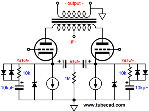
Push pull 6P1P with CCS Cathodes.
Using 20 ohm set resistor for 61 odd ma, 3 tubes bias up to 11-12V, one tube comes to 3v, but flows 52ma. the 1.25V reference is only 1.09V, tried different tubes, different LM317, with and without bypass caps (the cathodes are cap coupled for class A, the LM317 is bypassed through opposing diodes/10k a la Broskie.
I'm not using the zeners, cause they blow up when they conduct (shorting the 10,000uf cap?) 🙂
Before this modification I was running 18V battery bias and FORGOT to ground the grids so they were floating in the first place with the appropriate arc over.
What's the chance I've ruined the OPT? They are small surplus trannies (10W) from an old HiFi. The only thing I haven't tried is swapping the OPTs.
Otherwise any ideas?
In other news I had a tube fail in a way today I've never seen before. It was fine for 45 seconds, then the power supply rail would lift 10V, then drop 10V. Swapped out the tube and all was well... Anyone ever seen this?
Update
The OPT primaries are all 270 ohm from side to centre, so I doubt it's that.
3 devices flow 60 ma with a 12V drop, but this one flows 52ma with a 3V drop. I don't get it...
The OPT primaries are all 270 ohm from side to centre, so I doubt it's that.
3 devices flow 60 ma with a 12V drop, but this one flows 52ma with a 3V drop. I don't get it...
Did you use individual CCS's per tube? Sorry, I can't see your picture, as you didn't upload it to your entry.
Best regards!
Best regards!
Have you swapped tubes around? Cheers, Erik
Yes. No effect.
Did you use individual CCS's per tube? Sorry, I can't see your picture, as you didn't upload it to your entry.
Best regards!
The schematic was an image link, not sure why you can't see it but I'll include it in this post.
As shown there is one CCS for each tube.
Attachments
1st: Have you tried only the CCS (LM317 + resistor), leaving all of the other stuff out...?
2nd: Is there something wrong with the socket? some "leak path"? Is the socket clean?
3rd: can you post a picture?
good luck with torubleshooting!
Erik
2nd: Is there something wrong with the socket? some "leak path"? Is the socket clean?
3rd: can you post a picture?
good luck with torubleshooting!
Erik
1st: Have you tried only the CCS (LM317 + resistor), leaving all of the other stuff out...?
2nd: Is there something wrong with the socket? some "leak path"? Is the socket clean?
3rd: can you post a picture?
good luck with torubleshooting!
Erik
1: Yes I did. I even replaced the CCS with a 180R resistor, it then dropped 8.3V
2: It's a relatively new socket (2nd set of tubes).
3: Further testing indicates the grid is -17V. The other 3 tubes are at 0V. The circuit uses 1k grid stoppers, and 100k grid resistors.
Hm, how can the grid be at -17V? What grid leak resistor are you using (there is none in the schematic)?
Hm, how can the grid be at -17V? What grid leak resistor are you using (there is none in the schematic)?
100k. I know! I've never seen that.
Hm. Strange design. Could someone please explain what the back-to-back diodes in parallel with the 10k and all together in series with the 10mF electrolytics do?
Best regards!
Best regards!
It allows for class A operation with bursts of clean power beyond strict class A.
https://www.tubecad.com/2011/08/blog0210.htm
https://www.tubecad.com/2011/08/blog0210.htm
The complete amp is basically the Acrosound 6L6 reworked for 6P1P and CCS instead of a shared resistor.
http://www.keith-snook.info/amplifier-hifi-schematics/Acrosound 6L6 Rebuild.pdf
http://www.keith-snook.info/amplifier-hifi-schematics/Acrosound 6L6 Rebuild.pdf
100k. I know! I've never seen that.
SO 0.17mA running through the 100k resistor. What happens when you shorten this resistor?
SO 0.17mA running through the 100k resistor. What happens when you shorten this resistor?
I'll let you know when I do it. I'm thinking of shunting a 1k resistor in parallel.
Hm. Strange design. Could someone please explain what the back-to-back diodes in parallel with the 10k and all together in series with the 10mF electrolytics do?
A reference to the original TubeCad article would be helpful.
Looking at the circuit: The CCS and Zener form a shunt regulated voltage source for the cathode of the tube. No surprise that the zener might "blow up", if the tube conducts too much for the zener to handle. Guessing that the anti-parallel diodes,10k,cap act as a filter to absorb noise from the zener. The diodes would allow rapid charging/discharging of the cap on start-up/turn-off?
Sheldon
What is the zener breakdown voltage? The zener doesn't even conduct during normal operation as the breakdown voltage should be higher than the expected cathode bias voltage. If the cathode biases to 12v, i would choose 15-18v zener. Did you put them backwards?
As the the tube biased to -8V when using 180R as cathode bias, this means the tube is fine. It's possible that you get a batch of bad LM317.. or shorted 10kuF cap. Remove the cap first (the one connected to back to back diodes) and see if it biases normally.
As the the tube biased to -8V when using 180R as cathode bias, this means the tube is fine. It's possible that you get a batch of bad LM317.. or shorted 10kuF cap. Remove the cap first (the one connected to back to back diodes) and see if it biases normally.
A reference to the original TubeCad article would be helpful.
It's in post #11, I'm not using the zener, the 10k/diodes isolate the cap from the circuit until the amp leaves class A.
What is the zener breakdown voltage? The zener doesn't even conduct during normal operation as the breakdown voltage should be higher than the expected cathode bias voltage. If the cathode biases to 12v, i would choose 15-18v zener. Did you put them backwards?
As the the tube biased to -8V when using 180R as cathode bias, this means the tube is fine. It's possible that you get a batch of bad LM317.. or shorted 10kuF cap. Remove the cap first (the one connected to back to back diodes) and see if it biases normally.
I've tried all of the above, and I'm not using the zeners. I've tried a different LM317 connected off chasis, same effect. I'll connect the 180R again and see what the grid voltage is. I'll check the cap too. It's possible that the 50v rating was exceeded when the tube arced over. Thanks.
It's looking like a bad grid connection. When i "pull" the connection with some force the grid voltage goes down and the cathode voltage climbs. I'm going to redo the grid circuit and post back.
- Status
- Not open for further replies.
- Home
- Amplifiers
- Tubes / Valves
- 6P1P, LM317 CCS cathode bias weird issue.