Hi Mrcloc,
I've worked on audio equipment for almost my entire life, starting on tube radios as a very young little fella. I've zapped myself more times than I can remember. One observation I've made several times is that the signal ground is normally the first thing that travels to copper heaven during a fault condition. In fact, every piece of equipment in the fault path tends to vaporize it's signal ground traces very quickly, as in SNAP! Gone. That then leaves the chassis ground as your only protection. You should see what a close lightning strike does. The damage is very distinctive.
With the above in mind, I can't accept any advice to "lift" the chassis ground system. One electrical path people can forget about are the knobs and headphone jack on the front panel. Here we are talking about even the small leakage currents that can kill some people. Wood is often a high resistance, not a near perfect insulator.
On finding a dangerous situation that the customer refuses to have repair, the law allows me to cut off the power plug (and I do sometimes, depending on the situation). Where I live, technicians are supposed to check the chassis leakage current before releasing the product. Almost no one does that test. I do simply because that feature is included on my variac / isolation transformer setup. It's a B&K 1655 "AC Power Source" that I was lucky to score on Ebay (of course I had to fix it, but the cost of it was such that I still got a really good deal).
That means there is another avenue available to break ground loops and add to the safety of your system. Isolation transformers. Some have another winding that you can use to correct your power voltage level. So an isolation transformer with the bridge rectifier and capacitor ground break circuit would probably eliminate most sources of noise in a system.
I run my signal sources off an outlet, and my amplifier has a direct line to the breaker panel. If you make sure they are on the same phase, you shouldn't have any hum issues. The same holds true if everything is plugged into the same outlet circuit.
-Chris
Earth ground loops in complex systems can cause one to pull one's hair out. I simply disconnect the earth of my amplifier, and the hum is gone. The amplifier is still earthed via the input.
Which as we have said is dangerous.
There are safe ground lift schemes like using a diodes bridge between circuit's ground and mains earth. Only in case of fault where their voltage difference exceeds 0.6V it conducts any large fault current. In normal state the connection is lifted.
Earthing (Grounding) Your Hi-Fi - Tricks and Techniques
And that is exactly my modification.
This isn't what you originally posted.
I think enough has been said on subject now. To reiterate, disconnection of the mains safety earth as a means to overcome some issue is unsafe practice and could in the worst case scenario result in someone being exposed to lethal voltage and current.
https://www.distrelec.de/en/control...4-vac-intronic-elf-ei-120-53-24vac/p/15600975
https://sklep.toroidy.pl/en_US/c/400-VA/89
Which one is better? I see so many amps with Torodial, is it a just a matter of choice or is Torodial the tested and preferred among the diyaudio guys.
This is a good thread http://www.diyaudio.com/forums/power-supplies/305291-toroid-ei-pros-cons-plz.html Wikkid has a way of getting the info he wants 😉😀
anatech and Mooly:
Well, I do simply disconnect the earth to get rid of the hum, but I don't want this to be my final solution.
As I said, the only possible connection to anything electrical on my amplifier is the signal ground on the RCA connectors. I have no knobs, no headphone jack, Speakon connectors, and an IEC connector with the fuse integrated.
My enclosure is 20 mm solid wood with a number of coats of polyurethane. The top panel is 6 mm glass. I only ever use a disconnected earth when the amplifier is connected to the computer.
One actual physical connection into the amplifier exists. I think that's pretty safe, especially if there is actually a mains earth connection, but I disconnect it at the moment, and know it is a temporary solution.
Hi vishalk,
E-I core transformers all the way. Even the "low frequency" toroid will have more line noise passing through it than the average E-I core transformer. The E-I core also has air gaps built in as part of how they are made. They don't have the saturation problems that a toroid design does.
The only thing a toroid design has going for it is the profile, which tends to be wide and flat, allowing a lower profile case if desired. However, you could still use an "R" core which will have some of the E-I core attributes along with a low profile.
A toroid is inherently a wide band device, but with relatively uncontrolled response due to the fact that the windings are bunched on the inside, destroying any coil layer designs. This also leads to higher interwinding capacitances. With an E-I core transformer, the electrostatic screens are far more effective because the layers in the windings can be controlled. Every wire ends up where it should be with more constant wire tension as well. Again, the very shape of a toroid works against the engineering as a problem to deal with.
One thing that I think about is that with an E-I core transformer, heat generated in the core can reach the ambient environment easily where it dissipates. You can even make sure the sheets are flat when the transformer is made, allowing some thermal compound to be applied between the transformer and the chassis. This arrangement effectively cools the core off more easily. With the toroid design, no portion of the core is exposed to anything beyond it's own windings. So, where does the heat go? Exactly
-Chris
This is a good thread http://www.diyaudio.com/forums/power-supplies/305291-toroid-ei-pros-cons-plz.html Wikkid has a way of getting the info he wants 😉😀
Some good stuff there, but about 80% of the discussion is about 'mains' filters.
For 'pro-toroid' arguments, there's an article on the Bryston website:
http://bryston.com/PDF/newsletters/Bryston_Newsletter_V8_4.pdf
Part 2:
http://bryston.com/PDF/newsletters/Bryston_Newsletter_V8_5.pdf
Bryston uses toroids in their amps - find a different company that uses E-I transformers and you'll probably find the opposite arguments.
For me, the choice usually comes down to:
1) What's readily available in the specs I need? See the selection of E-I 400VA 18-0-18 transformers available, for example. (Hammond 167T36?)
2) Cost (including shipping).
For the design you're going to build, see what you can find at the right voltage and VA rating.
Very small data sample:
Whenever I've had 'mechanical' or 'electrical' hum problems from a transformer, E-I has been the installed transformer. Toroid transformers on the same AC circuit haven't had the same problem.
I do prefer the mounting arrangement for 'standup' E-I transformers, the laydown style are the worst. Toroids are OK, but generally need to be well hidden, which is the style anyway in SS gear.
Last edited:
Thanks anatech.
I was leaning towards going the EI route. Next is planning what capacitors to use, i like the idea of supercapacitors. Not sure if the technology has improved and you can get low ESR, i know they are used in class d.
My thoughts are its needed for filtering but supercaps act like a battery. Anyone on here used supercaps successfully?
Surely having the power supply in the same enclosure is also a disadvantage due to magnetic fields and other bad interference issues they would cause?
If i was to make it all in one enclosure isn't it better to have all the power supply shielded and away from the amplifier boards?
any thoughts on soft start?
Sorry, work and family life, when i have a chance to think about my diyaudio project these thoughts cross my mind.
Looking more into it, i'll need some more toys (tools) like an oscilloscope?
I mean how else am i supposed to test the amplifier? If i am going to do this i want measurable tests to prove i haven't built a poor working amp. Infact when you have built the amplifier what tests would one do?
Just doing some simple CAD designs to visually get a idea of what i want to build, i'll be sure to post them.
Thanks!
Hi vishalk,
E-I core transformers all the way. Even the "low frequency" toroid will have more line noise passing through it than the average E-I core transformer. The E-I core also has air gaps built in as part of how they are made. They don't have the saturation problems that a toroid design does.
The only thing a toroid design has going for it is the profile, which tends to be wide and flat, allowing a lower profile case if desired. However, you could still use an "R" core which will have some of the E-I core attributes along with a low profile.
A toroid is inherently a wide band device, but with relatively uncontrolled response due to the fact that the windings are bunched on the inside, destroying any coil layer designs. This also leads to higher interwinding capacitances. With an E-I core transformer, the electrostatic screens are far more effective because the layers in the windings can be controlled. Every wire ends up where it should be with more constant wire tension as well. Again, the very shape of a toroid works against the engineering as a problem to deal with.
One thing that I think about is that with an E-I core transformer, heat generated in the core can reach the ambient environment easily where it dissipates. You can even make sure the sheets are flat when the transformer is made, allowing some thermal compound to be applied between the transformer and the chassis. This arrangement effectively cools the core off more easily. With the toroid design, no portion of the core is exposed to anything beyond it's own windings. So, where does the heat go? Exactly
-Chris
The best defence against magnetic fields is distance. The only test gear you really need if you are building an amplifier from an established design is a multimeter. A bulb tester is highly advisable for initial power up. What are "super capacitors"?
Soft start is good idea with a toroid or if you have a large capacitance to charge.
The main tests are to make sure you haven't a large dc offset on the output, and to check/set the bias
Soft start is good idea with a toroid or if you have a large capacitance to charge.
The main tests are to make sure you haven't a large dc offset on the output, and to check/set the bias
Last edited:
Chassis, enclosure
SYCAO 2412 class a aluminum amplifier enclosure case diy amplifier chassis | eBay
WA 75 aluminum enclosure amplifier class a amplifier enclosure DAC chassis
Does it need to be this big in terms of the heat sinks? I thought i would initially buy an enclosure to put the parts in and get it going until i have my own enclosure designed and machined.
Does it need to be this big in terms of the heat sinks? I thought i would initially buy an enclosure to put the parts in and get it going until i have my own enclosure designed and machined.
Which amp are you going to build?
Once you decide that, look at the chassis/heatsinks in the diyaudio store and check the build threads - often the heatsinks from 'the store' are referenced....pick up the dimensions of the heatsinks from there and you can get started.
There are also sites that you can use to calculate the heatsink size you need, once you know how many watts of heat you need to dissipate, and how much temperature rise above ambient your devices can stand.
Last edited:
Going to build a Jean Higara super class A 30w!
Which amp are you going to build?
Once you decide that, look at the chassis/heatsinks in the diyaudio store and check the build threads - often the heatsinks from 'the store' are referenced....pick up the dimensions of the heatsinks from there and you can get started.
There are also sites that you can use to calculate the heatsink size you need, once you know how many watts of heat you need to dissipate, and how much temperature rise above ambient your devices can stand.
The enclosure is such a big part of the build that you may decide to just build another amp for your custom-built enclosure.I thought i would initially buy an enclosure to put the parts in and get it going until i have my own enclosure designed and machined.
Going to build a Jean Higara super class A 30w!
Well, that's one decision made!
https://www.youtube.com/watch?v=MYllDFkPWjk
https://www.youtube.com/watch?v=_KBJMzHDYco
educational builds gave me some insight
https://www.youtube.com/watch?v=_KBJMzHDYco
educational builds gave me some insight
The enclosure is such a big part of the build that you may decide to just build another amp for your custom-built enclosure.
hahaha i think you're right, gives me an excuse to build a firstwatt amp.
Well, that's one decision made!
hahaha i think you're right, gives me an excuse to build a firstwatt amp, one of several more decisions to go!
Last edited:
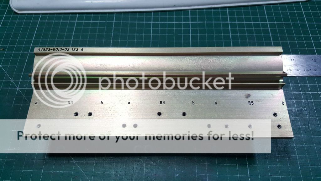
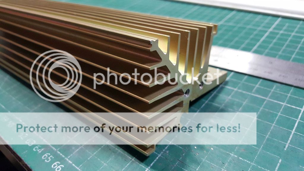
Heat Sinks.
Well these came along and couldn't say no, these are heatsinks from a military airplane cockpit instrument panel 😀.
Think i'll call the amp Jean Hiraga Super Aviation or Avionic series.
Eitherway the enclosure will be based around these heatsinks.

Well these came along and couldn't say no, these are heatsinks from a military airplane cockpit instrument panel 😀.
Think i'll call the amp Jean Hiraga Super Aviation or Avionic series.
Eitherway the enclosure will be based around these heatsinks.


Where capacitance is concerned, higher values decrease the conduction angle and generates extremely high but short current spikes in the the filter capacitors and transformer. The noise will be higher in frequency (bad) that is much more difficult to clean up. If you go with more reasonable capacitance, you will mainly generate mains frequency related noise and some harmonics. Lower frequencies are easier to take out with a regulator and don't couple as easily to other circuits.
Having a big dislike for umbilical cords, I'd build a one box solution using reasonable sized filter capacitors. You can create a box for the power supply on the inside. This design has been used very successfully by brands such as Yamaha and Nakamichi along with several others. So a little thinking and you can avoid most pitfalls. Huge capacitance is a pitfall.
Capacitors don't act like a battery unless you charge them with a low crest factor current. Charging from a rectified AC source will generate current pulses you really don't need or want. The larger the capacitor is, the higher it's inductance, which adds more to the current pulses generating large voltage peaks.
This is stuff that was well understood in the 50's through 70's. We have recently forgotten all those lessons.
-Chris
Where capacitance is concerned, higher values decrease the conduction angle and generates extremely high but short current spikes in the the filter capacitors and transformer. The noise will be higher in frequency (bad) that is much more difficult to clean up. If you go with more reasonable capacitance, you will mainly generate mains frequency related noise and some harmonics. Lower frequencies are easier to take out with a regulator
....... Huge capacitance is a pitfall.
It's interesting to note the difference between the Hiraga PS capacitors (high capacitance) and the Nelson Pass approach, which seems more reasonable to me.
The high capacitance power supplies remind me of the 'car audio' enthusiasts with some of their ideas.😱
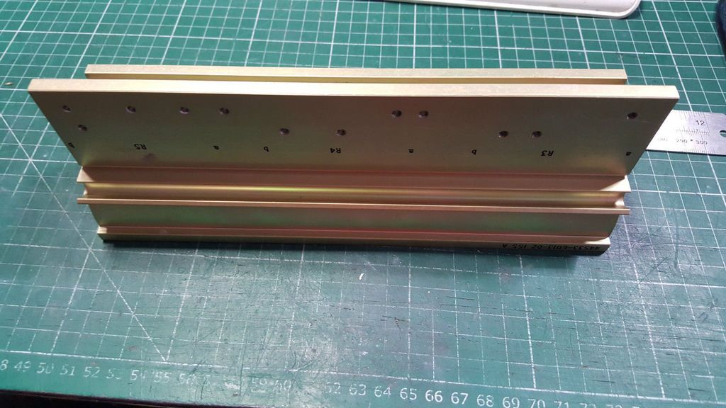
Well these came along and couldn't say no, these are heatsinks from a military airplane cockpit instrument panel 😀.
Think i'll call the amp Jean Hiraga Super Aviation or Avionic series.
Either way the enclosure will be based around these heatsinks.
They look very nice.
How much do they weigh?
Are you going to mount them vertically or horizontally?
- Status
- Not open for further replies.
- Home
- Amplifiers
- Solid State
- What Class A amplifier, 10-20 watts for fullrange speakers.