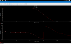
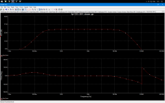
This is it with 0.1 ohm, 470mF and without input filtering.
This time I made it to show the vertical gain scale in decibels.
What are you seeing with this phase margin? stableness ? Im guessing yes.
If yes, which is more important: the OLG analys or the normal one? Im guessing the OLG is more important.
Im guessing that you see how many dBs is the gain where the phase shifts to other dimension.
Attachments
Last edited:
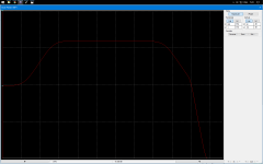
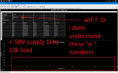
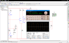
I' m not so familiar reading the plot in Multisim, the phase seems to look alright but the gain, was that 100dB? and the cut off frequency seems to be a little short. It slopes just after reaching 10khz.
I do think you cant feed much amplitude in there. it'll clip instantly.
I do think you cant feed much amplitude in there. it'll clip instantly.
I' m not so familiar reading the plot in Multisim, the phase seems to look alright but the gain, was that 100dB? and the cut off frequency seems to be a little short. It slopes just after reaching 10khz.
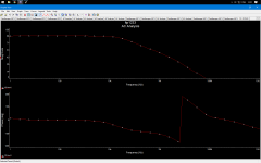
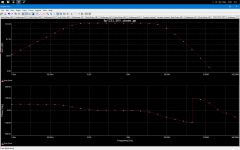
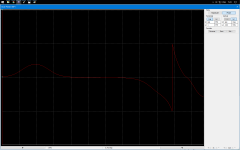
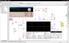
This is the open-loop AC, look post #15 for the normal.
I do think you cant feed much amplitude in there. it'll clip instantly.
I didn't understand this. You mean it cannot output close to rails swing ?
----------------
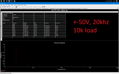
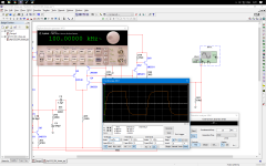
I like very much this. The 2nd attach is the OLG plot with 0.1r and 470mF.
The 3rd is the normal AC with 1k and 470u.
Im attaching the multisim project file too, if smb wants to play with.
It need v.12 of Multisim to open it.
Attachments
Last edited:
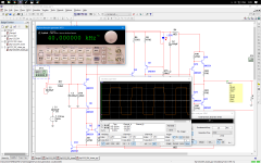
It's hard to see much without the grid turned on, but it looks like your gain margin is something like -40 dB and phase margin close to -180°. Nice oscillator you've got there.This is it with 0.1 ohm, 470mF and without input filtering.
This time I made it to show the vertical gain scale in decibels.
What are you seeing with this phase margin? stableness ? Im guessing yes.
If you have non-zero closed-loop gain, the interesting point for phase and gain margin is not where OLG crosses zero dB but rather where it's equal to closed-loop (noise) gain. Or that's my understanding of it, anyway. That is what the whole deal with unity gain stability is about. If you don't actually need it, you can get better GBW and slew rate in a higher-gain application.
Even with these relaxed criteria it looks like you're just about in instability territory though.
Oh, and it's normal for the phase to wrap around when it crosses -180°. A smarter phase display function might piece it back together so you get a continuous curve.
Last edited:
This is the open-loop AC, look post #15 for the normal.
I didn't understand this. You mean it cannot output close to rails swing ?
It was a confusion it says in the plot AC Analysis but if it was OLG it looks good I just do not understand the phase it says 0 you need to find the equivalent phase at 0dB.
To calculate the phase margin the formula is;
Phase at 0dB crossing minus 180° for example the phase at 0dB crossing (this is below unity loop gain) is 86° then that becomes 86°- (-180°)=94°
OK, thanks de Ocampo.
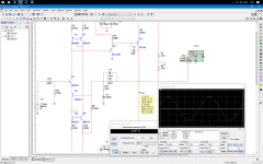
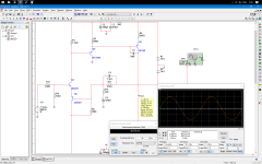
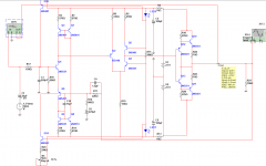
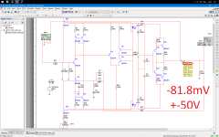
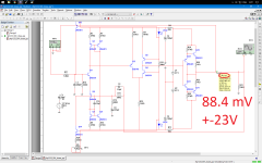
Im attaching a circuit like the last one but without the CMs. It seems that it gives the almost same THD, so you are saving 4 transistors this way.
R6 is better to be 1k in this one.
Can't wait to test it real life and maybe I'll test it now. I have a working LTP+CM front-end on a prototype PCB that I can modify to this.
The problem is I don't have 1Mohm resistor and I need to go with 2x 470k
Attachments
Last edited:
Do not rush things up, like sgrossklass has stated you might be building an oscillator. You need to figure out the stability first, it seems what you have done so far is a work on THD figures. There is a very good teaching lesson here http://www.diyaudio.com/forums/software-tools/101810-spice-simulation.html by andy_c on Loop gain analysis (beginning post #87 I think) You may want to check it out first.

What is the difference between unconditionally stable and conditional stability?
I'll try to answer and please come in a correct my errors in this.
Unconditional stability requires that the open loop gain must drop below unity loop gain before the phase has reversed at 180degrees. AND the slope in the gain at the crossing of unity gain must be less than -9dB/Octave.
Conditional stability is a lesser region where the closed loop gain dropping to unity (zero dB) is used as the reference frequency where the phase has not yet reversed @ 180degrees.
I thought unconditional stability means it is stable and will remain stable when dropping the loop gain. Conditional stability means it is stable but may oscillate if the loop gain is reduced - this is because the gain locus crosses the axis above the (-1,0) point but then returns back again to eventually drop below it, so dropping the loop gain moves the critical point into the unstable region.
I am talking about a Nyquist plot. This is more work than a Bode plot but can give better information.
If the loop gain locus crosses the axis more than once (i.e. three times) then you can have a situation in which loop gain exceeds unity at 180 degrees phase shift yet the loop may remain stable. If so, this is conditional stability. This is counter-intuitive, yet true.
Unfortunately, I think there is another quite different meaning for conditional stabilty: loop gain is less than one so no matter how much extra phase shift you add it will still remain stable. I think you may have been referring to this one?
Unfortunately I don't know.
But to try to understand what Sgross posted
But to try to understand what Sgross posted
I need to know more.If you have non-zero closed-loop gain, the interesting point for phase and gain margin is not where OLG crosses zero dB but rather where it's equal to closed-loop (noise) gain.
But to try to understand what Sgross posted I need to know more.
I think there is nothing crucial about what sgross posted. It is what it is and the approximation has no serious consequences afaik.
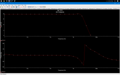
Well, try to read this one. This time I turned the grid on for ease and found out there are markers.
Attachments
Last edited:
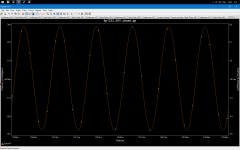
Dont oscillate with squares. Is it stable ?
Attachments
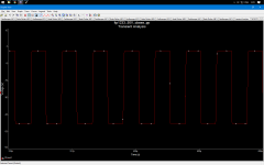
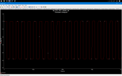
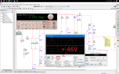
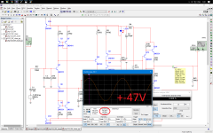
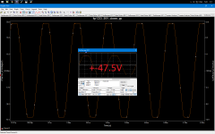
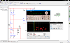
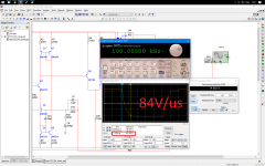
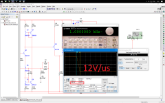
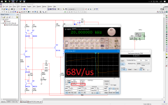
slew rate measurements.
I have a question about my output, ppush-pull stage, driven with a diamond buffer and biased at 3 mA.
The question is: Is it working as a normal 3 mA emitter follower stage but more current capable? class A, right?
Btw it oscillates with square waves without C10 which one I tried for joke. It seems that it compensates it well.
Attachments

Last edited:
- Status
- This old topic is closed. If you want to reopen this topic, contact a moderator using the "Report Post" button.
- Home
- Amplifiers
- Solid State
- LTP works better with more current in the right collector