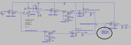
This is a basic general question about where to put the effects loop in a pre-amp I am designing. Basically, I thought I would put it at the end of the preamp, right before the master volume. I have shown this a schematic you can see. Also, I was wondering how this is done. I was thinking I would get one of those 1/4 jacks with 3 tabs on it, so when you plug the 1/4 plug in, it disconnects and the signal goes through the effects cable. Am I on the right track here as far as how to implement an effects loop in this circuit?
Attachments
Last edited:
Basically this looks ok.
I'd rather use two 1/4 jacks with two "rings", this gives you the option to extract a "pure" signal for e. g. recording.
Effects send impedance might be an issue too.
I'd rather use two 1/4 jacks with two "rings", this gives you the option to extract a "pure" signal for e. g. recording.
Effects send impedance might be an issue too.
Effects send output impedance.
Yes, I see that clearly now, I think I will need to address the output impedance of the effects send. I guess I will have to put a buffer right before the effects send.
About the trs type 1/4" jack/plug with 2 positives and a ground. If someone plugs in a mono jack, into the effects send or return, couldn't that ground out one of the positive terminals? I wonder what the most common thing is to do for an effects/send return.
I like that idea though, because that would be great for live recording or even a line out for live performance.
With the dual jack version, you'd use TS jacks. Switch from clean to FX would be on FX return.
You could even take the concept a step further: two balanced XLR outputs; one before FX send, the other one after FX return...
You could even take the concept a step further: two balanced XLR outputs; one before FX send, the other one after FX return...
Last edited:
I see. I know this is very basic, but it looks like you are saying people use a stomp switch to switch the effects loop on an off in some designs.
I was thinking just to place a simple loop before the output. And as far as turning it on and off, that would be the responsibility of the pedal(s) in the loop.
I was thinking just to place a simple loop before the output. And as far as turning it on and off, that would be the responsibility of the pedal(s) in the loop.
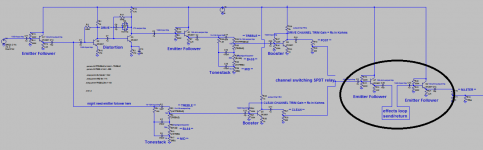
Here is the added buffer before the effects loop.
Looks good.
Regarding the stomp switch - sounds like a good idea 🙂
Your large question: FX should go out at slightly above pickup level; guitar-cord devices may not take a lot more and sure do not want less.
But there are other details you should ponder more.
The pickup input impedance is under 100K, rather low by most standards.
For many reasons, a JFET is a dandier device than a BJT for guitar input. The OSI for a high-hFE BJT at 1mA is nearer 1K than the 10K-100K source impedance of a guitar. BJT inputs sure can be done but not drop-in simple.
I will ignore the dirty channel because that's hard thinking.
The clean channel takes pickup and buffers it gain of 0.98. (I don't see how you would want another emitter follower here.) Then it goes to a *lossy* tone stack. Signal out of this will be LOW. Lower than what came from the guitar. Low compared to thermal hiss in tone stack parts (even though you did shift the impedance down some). Usually you do NOT want signal to get lower than what came from the guitar, or you are likely to be down in universal hiss.
The booster following that has an input impedance (Miller effect) of way-way under 220K, possibly lower than 22K. This is probably a heavy load on the tonestack, so you won't get the expected responses. (I can't be sure because the image is blurry and so is my eye.)
The only Gain control in the Clean path is *after* the buffer. If a real-stong input overloads the buffer, you have no knob for that.
I would *prefer* not to send pot wipers out to the outside world. Wiper impedance varies a lot, which means it will work different for different loads. 0-10K may be an acceptable range.
The classic g-amp input takes gain right from the pickup, then tone and volume, then a recovery stage. If you have 300V systems, gain of 50 in front works well, gives high level through tonestack so your recovery stage is not down in the hiss. But by extension, a 30V system may not like gain more than 5; a 10V system may input-clip with a hot guitar and gain of just 2. What many many SS inputs do is design a variable-gain stage which can turn up to 10 if needed but down to unity to stay clean on strong inputs.
I strongly advise you to PLAGIARIZE ! Call it "research" if you want. But knowing what paths were fruitful for the many dozen designers before you may clarify your own path (or turn up something to adopt).
An excellent (now aging) SS discrete guitar preamp is the original Roland Jazz Chorus 120. The one without chips. The whole turkey with chorus and stereo is a bit much to absorb in a day, but the preamp is reasonably clear.
Attachments
Last edited:
- Status
- Not open for further replies.
- Home
- Live Sound
- Instruments and Amps
- Where do i put effects loop in guitar preamp circuit?