Probably you're right. Oppermann, the German dealer we've bought these amp kits from about 40 years ago, only mentioned possible stability issues if resistor R20 were reduced to less than 33 ohms. We used 100 ohms as this was appropriate to our purposes.
Maybe the simulation models you used don't apply to the original active devices that were available those days? It is, e.g., well known that a nowadays' 2N3055 doesn't behave identically to it's 40 years old originals. And do you really have true sim models to these metal can (TO-78, I believe) small signal transistors? Maybe all that makes some difference between my working build and the marginal stability in your sims.
If you're interested, I will send you a scan of the original schematics, PCB layout and build advice per PM.
Best regards!
Of course I have no original simulation models of this 40W Edwin.
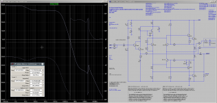
I just wanted to know why my home-brew variant of this circuit needed a 20pF miller cap across Q12 base to stop oscillations. Today I know why. The circuits GM/PM betters if we use better/newer/faster transistors. Still far away from stability of a modern designed amplifier but maybe stable enough if those amplifier kits have been built from the original kit parts.
Using models only from Bob Cordell this amp looks like to have a GM of 42 degree and a PM of 37 degree but wasn't stable at all. Heavy oscillation on negative half wave.
Adding a 100nF capacitor C8 across collector/emitter of Q10 cured the oscillation. Heavy dependent on used transistor models... 😱
BR, Toni
Attachments
Interesting. I'd guess this prevents drive impedance for the bottom output from going overly inductive as a result of finite bias transistor fT.Using models only from Bob Cordell this amp looks like to have a GM of 42 degree and a PM of 37 degree but wasn't stable at all. Heavy oscillation on negative half wave.
Adding a 100nF capacitor C8 across collector/emitter of Q10 cured the oscillation. Heavy dependent on used transistor models... 😱
BTW, current through Q12 must be minuscule (and heavily device-dependent). I'd really give that an emitter resistor down to Q4 emitter... even a 6k8 should be quite sufficient.

Thx for sending me a copy! Asc file is now verified to be the same circuit....
If you're interested, I will send you a scan of the original schematics, PCB layout and build advice per PM.
...
It took "only" 36 years to get/find a copy of the original build instructions. 😉
BR, Toni
You're welcome. Toni 🙂!
Btw, did the additional 6k8 resistor at the input Darlington stage also cure the stability issues in your sim?
Best regards!
Btw, did the additional 6k8 resistor at the input Darlington stage also cure the stability issues in your sim?
Best regards!
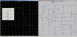
Stability hasn't bettered but slewing behaviour. Still heavy overshoot as a sign of low GM/PM.
I'm still in the process of reactivating my old homebrew amplifier then I'm able to do some measurements I couldn't do at that time (1980/81). Some lytics need to be renewed - the amplifier was in use about 30 years till 2010.
BR, Toni
I'm still in the process of reactivating my old homebrew amplifier then I'm able to do some measurements I couldn't do at that time (1980/81). Some lytics need to be renewed - the amplifier was in use about 30 years till 2010.
BR, Toni
Vintage series: discrete TAA761A opamp - 2N3055 quasi compl. amplifier - 50W@4R
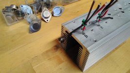
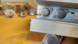
Mounted some RCA type 2N3055 (1979) on heatsink for bread board testing the TAA761 based amplifier.
The last time I have mounted such TO3 transistors is now about 32 years ago 😉
hFe at Ic 5mA is about 135
Vbe is 0.544 at Ib 5mA
Vcesat is 0.04V at Ic 5mA and Ib 1mA
Does anybody know the cheap "TP 2N3055" (on other side "Mexico") shown in background. The hFe measured for 10 pcs goes from 9 to 130. Maybe I have bought fakes 35 years ago? 😱
Attachments
Last edited:
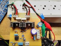
Vintage series: discrete TAA761A opamp - 2N3055 quasi compl. amplifier - 25W@4R
Running!
Really amazing to see such old parts (2N3055 and TAA761A) working out of the box. The RCA 2N3055 are from 1979, the TAA761A about same year.
Unfortunately the slewrate of the opamp is asymmetric and very low.
But 1 kHz full power is possible.
Some measurements with 4R resistive load with 35V stabilized single supply:
THD1k 1W@4R 0.01%
THD1k 25W@4R 0.008%
SNR in reference to 25W@4R:
The "new" circuit uses TMC compensation and is working out of the box. No signs of instability even during clipping.
Have fun, Toni
Running!
Really amazing to see such old parts (2N3055 and TAA761A) working out of the box. The RCA 2N3055 are from 1979, the TAA761A about same year.
Unfortunately the slewrate of the opamp is asymmetric and very low.
But 1 kHz full power is possible.
Some measurements with 4R resistive load with 35V stabilized single supply:
THD1k 1W@4R 0.01%
THD1k 25W@4R 0.008%
SNR in reference to 25W@4R:
- 100dB full bw
- 105dB 80k bw
- 113dB A-w
The "new" circuit uses TMC compensation and is working out of the box. No signs of instability even during clipping.
Have fun, Toni
Attachments
Last edited:
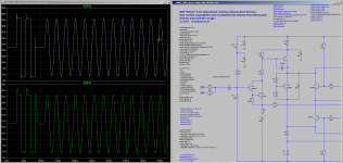
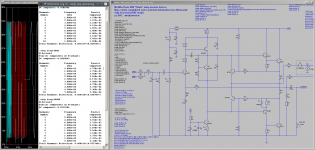
TMC compensation works as simulated.
Slewrate of the TAA761 with gain 19 is awful bad 0.4V/µs rising edge and 3V/µs falling edge. Far away to reach 20kHz full range. But for a homebrew amplifier in the early 80's good enough listening to FM radio, tape or vinyl even with standard miller 33pF. The SNR values where very good for that time (see measurement above)
THD1k 1W@4R 0.11%
THD1k 25W@4R 0.04%
Last edited:
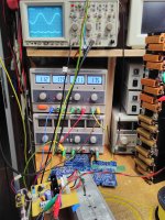
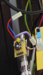
What's the little assembly down in the bottom left corner?
Is it an adjustable test signal voltage coming via a BNC cable from your signal generator?
Yes - added a 2.5k trim potentiometer and several pins to be able to connect probes.
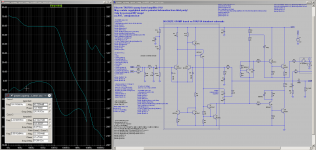
vintage series: modified Edwin 40W
The old "Edwin 40W" can be bettered with some small changes.
The old "Edwin 40W" can be bettered with some small changes.
- add VAS CCS
- input bias modified which dramatically betters PSRR
- RF input filter
- output zobel
Attachments
Last edited:
Hi Toni,
congrats on your successes 😉!
I've been stumbling over your pics showing the collectors' connection of your TO-3 devices, as I'm accustomed to do it in a slightly different way: Instead of routing the cables through additional holes, I mount the isolation bushings beneath the sink. So I can connect the collectors at the same side as the emitters and bases.
You don't want to tap the mounting holes here, though.
Best regards!
The old "Edwin 40W" can be bettered with some small changes.
BR, Toni
- add VAS CCS
- input bias modified which dramatically betters PSRR
- RF input filter
- output zobel
Or you might just build a "good" circuit and stop wasting time trying to polish a turd.
- Status
- Not open for further replies.
- Home
- Amplifiers
- Solid State
- Discrete TAA761A opamp - 2N3055 quasi compl. amplifier - 50W@4R