A bigger heatsink I have. 🙂
Is there a better regulator (lower dropout) for this application?
Attachments
If I remember correctly, 1.5K, but with 20mA plate current!! There's little it can't drive.
Can you tell me the mu of gain of 6V6 tube itself?
6V6 SRPP
Salas,
Between 6V6 SRPP and 6V6 direct plate output circuit, which one do you prefer the best?
Thanks!
Salas,
Between 6V6 SRPP and 6V6 direct plate output circuit, which one do you prefer the best?
Thanks!
Salas,
Between 6V6 SRPP and 6V6 direct plate output circuit, which one do you prefer the best?
Thanks!
Direct
Can you tell me the mu of gain of 6V6 tube itself?
Near 10 in triode mode
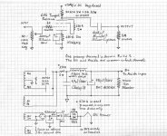
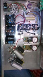
Can I use the attached power supply circuit plus regulator with 2 x 6V6 tubes for the 6V6 linestage??
How can I adjust the power supply from 300v to 340v??
It is a tubed regulator already. There is the 200K VR on quick look but I don't know the well working voltage drop margins. Anyway, 300V is still useful for this preamp. About its max well regulating Vout and its max pass current you should verify with its designer. This preamp would be happy with 60mA available for two channels.
How can I adjust the power supply from 300v to 340v??
O boy. It should regulate good enough but that is one beast of stealing power. The 3 k alone in the series reg burns some 15ish Watt. Interesting grounded grid high mu to inverting low mu high current section though.
And yes the 200 k VR adjusting the 6V6 grids as shunts via 12ax7b section but that is only designed as a fine tuning.

Don't allow much dissipation across Q1. It is not a low Θjc device. It would heat up fast enough even if you had boosted its sink mass. About 1.5-2W max allowance will be prudent. In other words if the raw DC is more than 370V for 60mA draw, burn some extra on a resistor somewhere in the raw section.
I don't know your chokes RDC and the expected drop across them but use a test load for raw DC representative of the reg's CCS mA setting. 10-20V drop across the reg is enough, 20-30V is not too taxing given the CCS draw is enough for such a preamp.
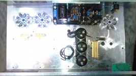
As you can see I have one reg over the other does not know how feasible is this.
Keep Q1s dissipation low then because the bottom sink will not have good air circulation.
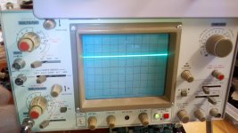
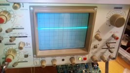
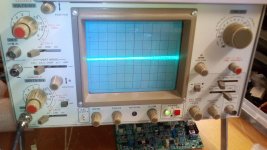
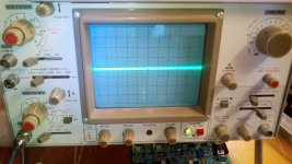
Here some measurments as 6V6 buffer
Τrafo 640 CT , 5V/3A, 10V/2A, 10V/2A
5AR4 SOVTEK
+330V, Heaters 6,12V, 6,21V
PSU 16uf+1K16uf to 1) 100uf+10H+100uf
2) 100uf+10H+100uf
1)probe X10 +330V
2)probe magnified X1 +330V
3)Output
4)Output
5)Heater
6)Heater
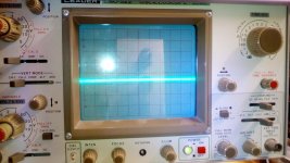
Τrafo 640 CT , 5V/3A, 10V/2A, 10V/2A
5AR4 SOVTEK
+330V, Heaters 6,12V, 6,21V
PSU 16uf+1K16uf to 1) 100uf+10H+100uf
2) 100uf+10H+100uf
1)probe X10 +330V
2)probe magnified X1 +330V
3)Output
4)Output
5)Heater
6)Heater
Attachments
Last edited:
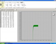
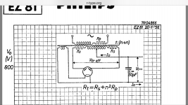
I have one question.
when we put the winding resistance on PSU Designer we calculate per plate Rt OR Plate to Plate resistance?
when we put the winding resistance on PSU Designer we calculate per plate Rt OR Plate to Plate resistance?
Attachments
Last edited:
- Home
- Amplifiers
- Tubes / Valves
- 6V6 line preamp