Hi guys.
I'm going to build a PGA2311 pre amp.
So I've got a few question about proper grounding.
RCA ground should be connected to chassis ground or signal ground?
How about IEC Inlet GND pin? It should float or should I connected it somewhere (where?).
Which place will be best for chassis connection? It should be direct connection or maybe something called ground loop braker (resistor in parallel with capacitor?).
How about XLR inputs? XLR GND should be tied to chassis or signal ground?
Thank you for helping me, because it's not so easy thread 🙂
This is well worth reading http://www.diyaudio.com/forums/diya...udio-component-grounding-interconnection.html
I saw that.
But my english is not perfect and I never done that before in stuff like this (mixed signals) with few power supplies.
But my english is not perfect and I never done that before in stuff like this (mixed signals) with few power supplies.
RCA ground is not a ground.
The RCA signal is a two wire connection.
The core carries the Signal Flow from the source.
The screen/barrel carries the Signal Return back to the source.
Break either of these wires and you lose the signal.
Inject interference into either of these wires and you add interference to the signal.
This is why the RCA barrel on the input/output socket is insulated from the chassis.
In addition, to minimise interference pick up, the two wires must be close coupled all the way along the whole route from source to receiver including at any intermediate terminations, such as the input socket and/or at the amp PCB.
Balanced impedance connections use two signal wires and a third using Pin1 to connect the chassis together.
Pin1 always goes direct to the chassis.
Pin1 does not go to the amplifier's inputs.
Pin1 always goes direct to the chassis.
Pin1 does not go to the amplifier's inputs.
The 3pin IEC socket has two power connections and one Protective Earth (PE).
The PE always goes direct to Chassis.
You are NEVER allowed to insert anything into this direct PE to Chassis connection. Make it permanent and never share this with another connector that you might want to dismantle at some later stage.
The PE must be a permanent direct connection.
The PE always goes direct to Chassis.
You are NEVER allowed to insert anything into this direct PE to Chassis connection. Make it permanent and never share this with another connector that you might want to dismantle at some later stage.
The PE must be a permanent direct connection.
Last edited:
Most importantly of all the IEC GND pin should be connected firmly to the chassis close to where it enters the case.
In that link above there are a lot of very clear drawings which I think you will be able to understand without good English. Please have a good look through.
RCA ground is usually connected to the chassis at the input.
XLR GND goes to the chassis
In that link above there are a lot of very clear drawings which I think you will be able to understand without good English. Please have a good look through.
RCA ground is usually connected to the chassis at the input.
XLR GND goes to the chassis
Hi guys.
I'm going to build a PGA2311 pre amp.
So I've got a few question about proper grounding.
RCA ground should be connected to chassis ground or signal ground?
To signal ground.
How about IEC Inlet GND pin? It should float or should I connected it somewhere (where?)...Which place will be best for chassis connection?
The IEC inlet ground should be wired directly to the chassis via a metal nut and washer secured bolt. This ground is for shock hazard safety protection.
It should be direct connection or maybe something called ground loop braker (resistor in parallel with capacitor?).
Ground loop breakers can be helpful, however, I suggest that given your unfamiliarity with the safety issues involved you leave ground loop breaker devices for later.
How about XLR inputs? XLR GND should be tied to chassis or signal ground?
Pin-1 should be tied to chassis/safety ground, not to signal ground. None of the XLR pins should connect to signal ground. Pins-2 and 3 should only connect to the balanced signal phases.
RCA Signal Return is NOT usually connected to the Chassis at the input..................
RCA ground is usually connected to the chassis at the input.
..............
Leach and Self show an alternative Voltage Reference where there is a non signal carrying wire from chassis to Signal Return. But even they show the TWO WIRE connection from Source to Receiver (amplifier PCB).
Hi Andrew, it is the Self connection at the chassis I am thinking of. I obviously need help with this! Why can the simplest things sometimes be so confusing? Ok, reference taken from RCA socket to main chassis GND connection, whilst socket insulated from chassis? "Connecting mains ground to the input ground gives maximal immunity against ground loops"
Last edited:
@Mark
That PDF is really helpful.
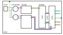
But not sure which point should be taken as a reference for grounding where there is five lines already used for that preamp.
Four analog PSU stages and one digital.
The nearest grounds juntion will be directly below PGA2311.
My PSU looks diffrent in terms of potential, because I don't have a proper negative supply or center tapped transformer with one bridge rectifier.
That reference point for PE cable and any other stuff is taken from main capacitors right after rectifier, but what to do when my PSU is diffrent?
That PDF is really helpful.
But not sure which point should be taken as a reference for grounding where there is five lines already used for that preamp.
Four analog PSU stages and one digital.
The nearest grounds juntion will be directly below PGA2311.
My PSU looks diffrent in terms of potential, because I don't have a proper negative supply or center tapped transformer with one bridge rectifier.
That reference point for PE cable and any other stuff is taken from main capacitors right after rectifier, but what to do when my PSU is diffrent?
How to wire a power amplifier, by Andrew Russell
There is no reference from signal return at rca to chassis, could this be a problem?
There is a connection at the T "to analogue small signal ground if required" - is this the reference connection and when might it be/not be required?
Mark, would it be better to take the ground from the analogue board to chassis nearer the PE connection?
Mark that look quite good, but I said that I'm not using center tapped tranformer 🙂
Point is which place in my design is the best spot to connect all this together to avoid problems 🙂
My analog PSU look like this (I'm just using more caps and diffrent voltage regulators).

Point is which place in my design is the best spot to connect all this together to avoid problems 🙂
My analog PSU look like this (I'm just using more caps and diffrent voltage regulators).
Last edited:
@Mark
Signal ground and chassis ground shoould not be connected together with PE cable?
I assume that PE cable from IEC Inlet should be connected shortest possible way with chassis?
But which point should be taken from PGA board to connect signal GND with chassis GND?
Signal ground and chassis ground shoould not be connected together with PE cable?
I assume that PE cable from IEC Inlet should be connected shortest possible way with chassis?
But which point should be taken from PGA board to connect signal GND with chassis GND?
Last edited:
It would be better to place the IEC and the RCA's on the same panel. Short connections are good, every wire is both receiving and transmitting into your circuits.
@Mark.
I'm going to place IEC Inlet and all IN/OUT socket on the same panel 🙂
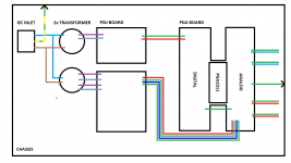
But I'm still unsure which point on my PGA board should be considered as a sweet spot for ground junction between chassis and signal.
There need to be a junction between digital ground and analog ground.
Maybe it will be good idea to connect chassis ground to that place? When digital meet analog.
I'm going to place IEC Inlet and all IN/OUT socket on the same panel 🙂
But I'm still unsure which point on my PGA board should be considered as a sweet spot for ground junction between chassis and signal.
There need to be a junction between digital ground and analog ground.
Maybe it will be good idea to connect chassis ground to that place? When digital meet analog.
- Status
- Not open for further replies.
- Home
- Amplifiers
- Power Supplies
- Proper grounding scheme