Simulate one output, so half, as mentioned, that is your curve.
Goal is to attenuate 400kHz around 40dB, so 100Hz or 1kHz isn't very likely to be affected.
Or take a look at Trevor's multisim simulation model:
http://www.trevormarshall.com/class-d-tutorial/
Goal is to attenuate 400kHz around 40dB, so 100Hz or 1kHz isn't very likely to be affected.
Or take a look at Trevor's multisim simulation model:
http://www.trevormarshall.com/class-d-tutorial/
Simulate one output, so half, as mentioned, that is your curve.
Goal is to attenuate 400kHz around 40dB, so 100Hz or 1kHz isn't very likely to be affected.
Or take a look at Trevor's multisim simulation model:
Trevor Marshall - Class D Audio Amplifier Design - TDA7498 Output filters
Yes I'm very familiar with Trevor's page, you may notice in fact that my filter I'm simulating and building is _almost identical_ to Trevors. There's a reason for that...
We should use a different filter for BD and AD modulation schemes too but that detail is for another day.
I'd rather simulate the actual filter I'm using TBH, however great half of it is I'm failing to see any benefit, unless I'm missing something. With that in mind please could you do a half-filter model of mine and post up the schematic + curves please, I'd be interested to see if it's any different and it would be very helpful. TIA.
In general, you get the most compact inductor for a given inductance if it's roughly square. I.e. length = diameter.
This is backed up on this page where they explain for a given length of wire the best cross-section shape is square, i.e. winding height = winding width.
An introduction to the air cored coil

I'm trying to find a source of small plastic curtain-rings or similar so I can make toroidal air-cored (plastic cored!) inductors. These have the benefits of less field interaction (eddy currents in nearby metal) and less turns (less capacitance and less resistance).
I tried my homemade bobbin coils in my test amp (a much modded Muse S7 - I keep modding it, it keeps on working!), and they work very nicely. The square waves (snubbed) going in are all very crisp with minimal overshoot. This amp is running at 351kHz and 24V, the inductors do get warm - about 10C above ambient I estimate as I can't find my IR temperature sensor.
Sound is accurate and dynamic, still a bit early to tell but it is sounding very good indeed. Very pleased with my first air coils, their constant inductance and lack of saturation seems to be having a subtle effect on the sound.
Time to stick some air coils in a better amp with a TPA3116 now I think, luckily I have a selection lying around to try 😉, after I've finished re-capping my old Box 550 speakers.
I'll post a pic when I get around to it.
Agreed.This is backed up on this page where they explain for a given length of wire the best cross-section shape is square, i.e. winding height = winding width.
An introduction to the air cored coil
I'm trying to find a source of small plastic curtain-rings or similar so I can make toroidal air-cored (plastic cored!) inductors. These have the benefits of less field interaction (eddy currents in nearby metal) and less turns (less capacitance and less resistance).
I tried my homemade bobbin coils in my test amp (a much modded Muse S7 - I keep modding it, it keeps on working!), and they work very nicely. The square waves (snubbed) going in are all very crisp with minimal overshoot. This amp is running at 351kHz and 24V, the inductors do get warm - about 10C above ambient I estimate as I can't find my IR temperature sensor.
Sound is accurate and dynamic, still a bit early to tell but it is sounding very good indeed. Very pleased with my first air coils, their constant inductance and lack of saturation seems to be having a subtle effect on the sound.
Time to stick some air coils in a better amp with a TPA3116 now I think, luckily I have a selection lying around to try 😉, after I've finished re-capping my old Box 550 speakers.
I'll post a pic when I get around to it.
And the Brooks coil gives the lowest wire length and thus the lowest resistance. (there's a 9:10 ratio in there, but almost square).
The Outside Diameter (OD) is roughly 4 times the width. The bobbin diameter is half the OD. i.e. Bobbin diam = 2C and OD = 4C & B=~10C/9
Last edited:
Yep all very useful good data, non saturating core , no bh pole flip and no barkhausen effect.
On my to do list is wrap long solenoid type and then horse shoe around into a torroid.
On my to do list is wrap long solenoid type and then horse shoe around into a torroid.
I thought they were impossible too, as I was trying to achieve this:
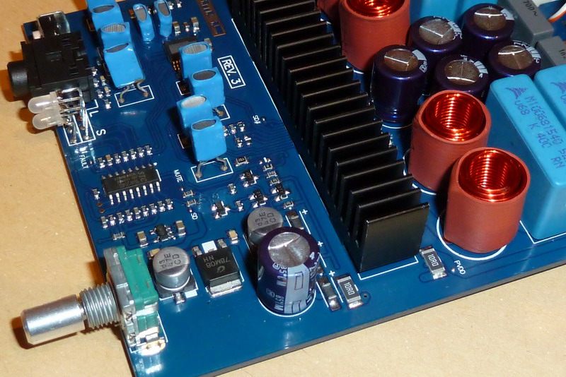
(The SMSL SA-60 pictured).
This is actually a poor design in terms of the inductor orientation, unless their intent was to have the inductor magnetic fields couple with each other.
That's the downside to air core inductors, the core material (air) does a poor job of containing the magnetic field.
Last edited:
I asked some while ago how we could make low capacitance air cored inductors, but got no replies. Is capacitance what you are referring to?
The two types of capacitance to be concerned about are inter-winding capacitance and start-end (probably a better term for this) capacitance. The only way to reduce those capacitances is to increase the spacing between the windings. However, increased winding spacing means less inductance per volume. It's the old tradeoff game 😉
Think of a fully wound, single layer toroid as an example. There is distributed capacitance between adjacent windings and there is also a capacitance between the first winding and last winding because they are physically next to each other.
Shielded inductors are better for class d amps because they contain the majority of the magnetic field in the core. This results in the less radiated magnetic field which may not be much in the far field but can affect the rest of the circuit that's near the inductor.
Yes, if you're lucky , you'll have nice crosscoupling into the front-end via the heatsink as receiver.
This is actually a poor design in terms of the inductor orientation, unless their intent was to have the inductor magnetic fields couple with each other.
That's the downside to air core inductors, the core material (air) does a poor job of containing the magnetic field.
Very true, I have taken care to arrange mine at 90 degrees to each other for minimum cross coupling.
Well the magnetic component is certainly there, but is the electrical bit present to create an EM wave? Also we are driving a fixed voltage square(ish) wave into the top rather than letting it resonate at a high Q to large voltages so I'm not sure how much EMI we'd generate.Makes a nice EMI radiator. 😉
But I have a radio-ham living nearby though and will try to get some results - he comes complete with a portable RF interference rig as many things cause RFI these days (Like those solar garden LED lamps for instance!), some plasma TVs, most SMPS and mains powered LED lighting controllers etc. Or so he tells me 😀.
A more serious matter for bobbin inductors is however that of eddy currents, I avoid having a metal plate at the end of mine, which means not aiming them at the PCB ground plane or any heat sink. A ground plane would of course act as a shorted turn although the coupling would be weak the issue is easily avoided.
By keeping an inch of feed wire on the coils it's easy to twist them into directions that miss the other coils and metal layers.
Currently I have my amps living in a metal box but a toroid winding is the obvious way to reduce RFI, resistance, cross coupling and eddy. I used sewing machine bobbins as they were easy - but plastic rings to wind Toroids should be findable and is the obvious next step.
It's also been suggested that the inductors will create a lot of heat but I haven't found this, just a little bit. For me they just sit there and work.
It's a bit like Russian closed cycle rocket engines like the NK-33. They were difficult to develop, Americans dismissed them as impossible, but they needed the advantages regardless (For their N1 moon-shot IIRC), eventually made them work, and they have huge advantages over the inferior closed cycle.
I just decided I'd be using air.
Last edited:
A small update on EMI and air inductors, had a chat with my local radio ham, a very experienced older chap who builds aerials, RF amplifiers, PSUs etc.
So he says that because they are inductors they'll round off any sharp edges and should operate in quite a well contained manner, even if the field is larger than with a ferrite.
Additionally as the fundamental of (say) 1MHz is 300 metres long in wavelength terms in aerial terms it's not really relevant as it's too small.
He said I may be able to pick up a nearfield signal from an AM radio but that was it. At some stage he'll pop round with the scanner (to check the house LED PSUs etc. as he's quite close and likes to enter DXing competitions) but he was entirely unconcerned and basically reiterated that it's basically an inductor and so looks after itself.
Which was nice. More updates as I get them.
So it looks like heat and EMI are not problems with air cores, that just leaves careful placement to avoid cross coupling. Because there is no core - cross coupling would I assume be very weak anyway and would have to drive against a switching output device to make any impact but each output remains crisp and true on the 'scope so I don't think there is an issue there on my boards.
The eddy issue with the bobbin type is still a concern - something I solved by leaving the leads a little longer and then twisting them so the axis (hole) pointed away from metal and PCB.
As for the field coming back to the input via the heatsink i certainly haven't experienced that on my boards but I've only two so far so it's a small sample size LOL.
So it looks like heat and EMI are not problems with air cores,
Have you tried this with i.e. 50V switching at 600kHz and 400W output load?
Have you tried this with i.e. 50V switching at 600kHz and 400W output load?
No, I've only noted the heat at normal listening levels with a 7489 (32V) and TPA3116 (20V).
At 400W I'd be looking for new speakers TBH.
Good idea though to measure the EMI on the detector while playing, I know they are always switching but the current will have to pass through them (to get to the speakers) so it's a good point.
My wire in the inductors is much thicker than that of the speaker voice coils though so I'm not expecting an issue with heating from higher powers but I doubt that I actually use more than about 1 or 2 Watts in normal usage.
I'm quite keen on more people trying air cored as my testing is obviously very limited, it's just been my observation however that the worst predictions of searing heat and local TVs being blotted out hasn't been the case in my usage of them.
I'd also be interested if my 'sounds lovely and sweet' is a measurable effect rather than just what I expected to happen based on the theory. I.e. removing the subjective element.
Maybe unrelated but i can hear my induction oven (cooking plate) at a distance of 150-200cm in my iphone 5 while having a call and these are aircoils as well.
Maybe unrelated but i can hear my induction oven (cooking plate) at a distance of 150-200cm in my iphone 5 while having a call and these are aircoils as well.
Interesting.
I looking it up too: Induction cookers: is EMF an issue? - MedicalPhysicsWeb
article said:the team found that the pot size used with respect to the size of the cooking area had a strong effect on the stray magnetic fields. Placing pots with diameters of 15, 20 and 25 cm on the same 21 cm cooking ring resulted in magnetic fields of 4.5, 2.4 and 0.9 µT respectively – a significant variation.
Could it be a saturation effect when adding a metal core (saucepan) ?
Perhaps it's the magnetic field picked up by the speaker and amplified by the feedback system of the iPhone's speaker amp. Difficult to stick an oven in a metal box though.
I wonder at the currents and inductance involved in the induction element. As far as I know class-D at idle has very little current (else it's efficiency would be rubbish) but perhaps the real test is like you suggested: into a load at high power levels.
Maybe a good EMI test would be to play some music in an air cored class-D amp and see if you can pick it up on the iPhone 😀
The main concern is the near field radiation and how it affects other circuits on the PCB, not the far field radiation which will be very weak at the power levels the amp is operating at. Susceptibility is another issue, but it's harder to control all the other external sources of radiation unless you shield the entire amplifier.He said I may be able to pick up a nearfield signal from an AM radio but that was it.
At lower power levels (<10W) heat should not be a big concern with the wire size you're using.No, I've only noted the heat at normal listening levels with a 7489 (32V) and TPA3116 (20V).
Two things here. First, eddy currents are caused by changing magnetic fields perpendicular to conductors. The magnetic field is not well contained in an air core inductor, so the only "fix" is to physically locate the inductor further away from the PCB. A shielded bobbin core inductor has most of the magnetic field contained in the core, so it should result in less eddy currents induced in other conductors.The eddy issue with the bobbin type is still a concern - something I solved by leaving the leads a little longer and then twisting them so the axis (hole) pointed away from metal and PCB.
Second, you want to minimize the area/length of any high frequency switching node for best performance. Longer leads do the exact opposite. This creates more EMI. It may not be something you care about, and it may not be much at low power levels, but it is there.
On the topic of air core inductors, here's an interesting study I just came across about toroidal air core inductors: https://engineering.dartmouth.edu/inductor/papers/pesc2007b.pdf
Although the fabrication method is not quite the same as wrapping a wire around a former.
Last edited:
If you pass an average current of 1A through a 1r0 inductor to your 8ohms speaker, then the average power to the speaker is 8W and the dissipation in the inductor's resistance is 1W.
But in general we don't listen to average levels as high as 8W and the inductor wire size is usually chosen to give much lower resistance.
0.5A equates to 2W of speaker power and through 100milli-ohms of inductor resistance results in average inductor dissipation of 25mW
Striving for lower source impedance for the speaker is usually the dominant reason for choosing a bigger wire size and this works for us in avoiding excessive inductor dissipation.
All good points BWRX, I read the Dartmouth thing too and nearly posted it earlier.
Don't think I have the skill to make 4 of those, or even 1 LOL.
Shielding the entire amplifier is easy but shielding the inductors needs to avoid interfering with their operation.
After what you've said I think I'll try to find brass screws for the Heatsink and PCB, no need to leave tempting bits of iron around when avoidable LOL.
I did find some 13mm clear rings for sale on eBay though for winding my own. When I get a bit of time I may look up the calculations.
I think my coil was about 1m long when unravelled, which is about 41mOhm. There are 2 coils in series though so that's really 82mOhm, bit still manageable.
Don't think I have the skill to make 4 of those, or even 1 LOL.
Shielding the entire amplifier is easy but shielding the inductors needs to avoid interfering with their operation.
After what you've said I think I'll try to find brass screws for the Heatsink and PCB, no need to leave tempting bits of iron around when avoidable LOL.
I did find some 13mm clear rings for sale on eBay though for winding my own. When I get a bit of time I may look up the calculations.
If you pass an average current of 1A through a 1r0 inductor to your 8ohms speaker, then the average power to the speaker is 8W and the dissipation in the inductor's resistance is 1W.
I think my coil was about 1m long when unravelled, which is about 41mOhm. There are 2 coils in series though so that's really 82mOhm, bit still manageable.
As an interesting aside as I was browsing the internet I came across this:
SoundStage! Equipment Review - TacT Millennium Digital Amplifier (6/1999)
Of which the internals are here:
TacT Millenium Mk II
Or specifically this picture:

Which appears to show a couple of nice air cored inductors casually sitting there. I note they are raised off the PCB a few millimetres and are not placed next to each other. Also they live in a metal box along with what appears to be the rest of the amp.
Looks neater than my DIY though LOL.
SoundStage! Equipment Review - TacT Millennium Digital Amplifier (6/1999)
Of which the internals are here:
TacT Millenium Mk II
Or specifically this picture:
Which appears to show a couple of nice air cored inductors casually sitting there. I note they are raised off the PCB a few millimetres and are not placed next to each other. Also they live in a metal box along with what appears to be the rest of the amp.
Looks neater than my DIY though LOL.
I would bet they have to be spaced off of the PCB because those inductors are made from flat foil.
This was also made for the "high end" crowd ($9-10k price) so it had to look high end as well. That's most likely the reason they used the foil inductors and boutique caps in the output filter.
The performance oriented amps today use gapped ferrite core inductors and film (not boutique) caps in the output filter.
- Home
- Amplifiers
- Class D
- DIY air cored inductors (how I made mine).