Hi everyone.
Sorry for mistakes in my English.
I have read plenty of threads about 6n23p preamps, I have listened to 6n23p preamp at home and I love the sound of it. I know that this is not a superb tube, but it has this "something" I like. The pre I was using was AVT2729 polish kit preamp. It sounded best with 6n30p tubes, but there was no "magic". Just the 6n23p tubes destroyes the sound the way I like. It will work as a preamp for my chipamp or d-class power stage.
And here is my question to You.
Please help me to choose a good preamplifier scheme for 6n23p (ecc88 equivalent) with as low output impedance as it is possible, as simple as it can be (I like simple audio things, the fewer parts, if applied properly, the better sound). And the most important thing - with as good sound as we can get from this tube.
I know, it may be a stupid question, but since I had contact with the preamp only once, I love the sound and I definitely want to build one, but not necessarily the AVT2729 one as there can be better schemes and better preamps using this tube.
Please help me.
Thank You.
Last edited by a moderator:
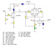
For the lowest possible output impedance you need a cathode follower for which this valve is very suitable; there must be many ecc88 cathode follower schematics on this site.
Below simple schematic from thread on this forum.
http://www.diyaudio.com/forums/tubes-valves/156789-gz34-otl-6n23p.html
http://www.diyaudio.com/forums/tubes-valves/156789-gz34-otl-6n23p.html
Attachments
Last edited:
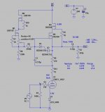
If you want real low output impedance (lower than CF), try Ale Moglia's cascode gyrator.6n23p (ecc88 equivalent) with as low output impedance as it is possible
Attachments
Check out the Tubcad.com site specifically the Aikido 12Vac. Easy to build, sounds good, and doesn't have very high voltages. Good for a first project.
Build detailed here (link shown for part 1 of a 4 part series):
Battle of the Cheap Line Stages – Part 1 | Wall of Sound | Audio and Music Reviews
Cheers, Steve
Also see ecc88 tube comparison on the same site.
Build detailed here (link shown for part 1 of a 4 part series):
Battle of the Cheap Line Stages – Part 1 | Wall of Sound | Audio and Music Reviews
Cheers, Steve
Also see ecc88 tube comparison on the same site.
Thank you very much for your help, I like the schematics you have shown above. I would like to reply to all of you:
kodabmx
I like the scheme given by you. I is very simple and has the lowest number of elements - kodabmx - could you please tell me where did you get this scheme from, was that ever built and how does it sound? Could you give me any forum threads about building and using (listening) this preamp architecture?
Steve Morley
This is a nice preamp, the thing I would change is power supply - making 80v out of 12v using caps and diodes. Why shouldn’t I use normal transformer with separate power supplies for the filament and for the tube anodes. If the 12v conversion is done only to make it easier to obtain and build or for the sound reasons? Because I can have any transformer I will need, 12V or 80V or any other voltage and current is not a problem. As I have learned from life experience (not that big 😉 - transformer is always very important part of the audio equipment structure (from the sound point of view). So - may I use normal power supply or this 12v conversion is the key to the best sound?
euro21
The scheme is interesting, I see it for the first time, but there are a lot of solid state components - so it is not a pure tube-amp but rather a hybrid. Am I right? How does it sound compared to full tube preamp?
Koifarm
This scheme is very close to the kit AVT2729 I have been listening to. I will read all thread carefully because I think this amp may be very good. The power supply part looks "classic" and the amp part looks like more advanced AVT2729.
piano3
Thank You for Your advice, do you have any schemes that you have soldered/listened to?
Thank you very much for your help, I like the schematics you have shown above. I would like to reply to all of you:
kodabmx
I like the scheme given by you. I is very simple and has the lowest number of elements - kodabmx - could you please tell me where did you get this scheme from, was that ever built and how does it sound? Could you give me any forum threads about building and using (listening) this preamp architecture?
This is a design of John Broskie of Tube CAD Journal.
There is a diode missing from this simplified drawing. I have included one with the diode. It acts to protect the second tube while it's not conducting. The diode becomes reversed biased and falls out of the circuit in operation. Without it the tube might arc over during warm up.
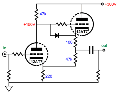
The other nice thing about this circuit is only one coupling cap!
EDIT: The 100 ohm resistor in this design acts to linearise the output at a cost of 100 ohm more Zo. If you need REALLY low Zo you can omit it but try it both ways, it's easy to short a resistor.
AFTERTHOUGHT: If you use 6N23P/6DJ8 tubes you can actually use this circuit as a descent 300 ohm headphone amp. If you use 6N6P and change the values accordingly you can drive 32 ohm loads.
Cheers.
Last edited:
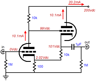
I really like this circuit. Constant current draw, very low distortion, low output impedance.
It is almost a Shmitt trigger, with positive feedback by voltage! 😀
It is almost a Shmitt trigger, with positive feedback by voltage! 😀
Yes, and to no good purpose.
All good fortune,
Chris
Newandrew,
By all means use a separate supply with the Aikido, if doing that run the B+ at about 150 volts. This will require some resistor changes for R2, 4, 8, 11. The 12Vac is a good introduction and easy, one transformer, way to start. It is deceptively simple and I thought I'd mention it as you are fond of the 6n23p (ecc88 equivalent). I can vouch for the 6n23p (ecc88 equivalent) effectiveness in the Broskie circuit.
Good Luck!
Steve
Yes, and to no good purpose.
All good fortune,
Chris
It eliminates the bypass cap. And according to Broskie it widens the soundstage and lowers the gain. It can be wired as normal by doubling the cathode resistor on the first tube, and connecting the second tube cathode resistor directly to ground. I've built three of these using 6SN7 or 6N1P and it indeed is an excellent sounding circuit.
It eliminates the bypass cap. And according to Broskie it widens the soundstage and lowers the gain. It can be wired as normal by doubling the cathode resistor on the first tube, and connecting the second tube cathode resistor directly to ground. I've built three of these using 6SN7 or 6N1P and it indeed is an excellent sounding circuit.
Well, you should read carefully what he said
"... more is what I got when I undid the capacitor resistor bypass and used jumper J5 instead. It was an amazing transformation. The sound stage went wide and deep—but the gain went down, ..."
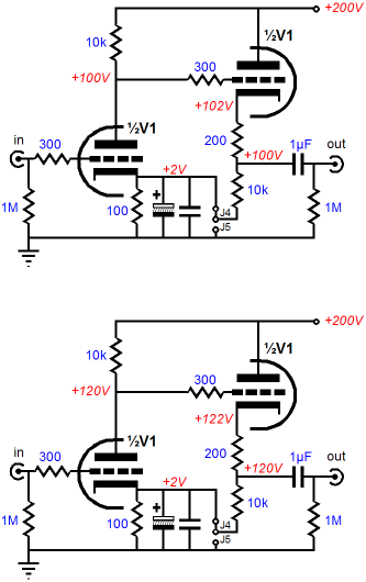
I've now read the Tube CAD CCDA article and the CCDA PCB user guide multiple times and I'm still confused, especially by that sentence.
I'm actually starting to belive that it's a typo and that it should read J4 and not J5. That would better match my understanding of the rest of the text, and the CCDA PCB user guide.
I'm actually starting to belive that it's a typo and that it should read J4 and not J5. That would better match my understanding of the rest of the text, and the CCDA PCB user guide.
newandrew, I have only built a separate line stage once (I consider separate preamps unnecessary now and put volume controls in the power amp) and it would certainly be much more complex than you are looking for; it is part of my fully differential main system and comprises balanced cathode followers (2 x 6SN7) with pentode constant current sinks (4 x 6P15P-ER) operating on 200V negative supplies. I built this just to see how it would work and wouldn't dream of building something like it now. I mean, 500V from the +ve to the -ve rails just for a unity gain preamp is crazy. I would use semiconductors now.
DC coupled positive feedback is a bad idea, even for oscillators. But to each their own.
All good fortune,
Chris
All good fortune,
Chris
newandrew, I have only built a separate line stage once (I consider separate preamps unnecessary now and put volume controls in the power amp) and it would certainly be much more complex than you are looking for; it is part of my fully differential main system and comprises balanced cathode followers (2 x 6SN7) with pentode constant current sinks (4 x 6P15P-ER) operating on 200V negative supplies. I built this just to see how it would work and wouldn't dream of building something like it now. I mean, 500V from the +ve to the -ve rails just for a unity gain preamp is crazy. I would use semiconductors now.
Why would you need 6SN7 if 6P15P is itself extremely linear tube designed for video amplifiers? 😱
Yes, Anatoliy, I quite agree! This was a long time ago and I didn't know of the great characteristics of 6P15P. I had just bought a box cheap thinking they would make good current sinks. Now I think it one of the best tubes in existence.
I really like this circuit. Constant current draw, very low distortion, low output impedance.
I am currently using a circuit similar to this with 6sn7 except the 2nd tube cathode resistor goes to ground instead of the the 1st tube cathode out.
The sound for this circuit is very good, IMO.
- Home
- Amplifiers
- Tubes / Valves
- 6n23p (and similar) low output impedance preamp