Is this even close to the way one would put a B- tail on a LTP or does there need to be a more definite reference to ground? Also what is the best way to apply FB?
Note C5 is a pole to avoid instability when FB is applied.

Note C5 is a pole to avoid instability when FB is applied.
Attachments
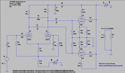
With B- available, try this way:
Remove R8 and R16 from the junction to R2 and connect those ends directly to ground.
R2 can be bypassed, connecting the cathodes directly to the tail resistor (51k).
You can then introduce NFB to grid-R16 junction, don't forget to remove C4.
Remove R8 and R16 from the junction to R2 and connect those ends directly to ground.
R2 can be bypassed, connecting the cathodes directly to the tail resistor (51k).
You can then introduce NFB to grid-R16 junction, don't forget to remove C4.
Check out Poindexter's "Musical Machine". That fine design evolved, over time, from a resistive tail to a CCS.
The "El Cheapo" I'm associated with has used a CCS tail, from the very beginning. The 'AQ5 shown in schematic is, for all practical purposes, a 6V6 in a 7 pin mini package.
The "El Cheapo" I'm associated with has used a CCS tail, from the very beginning. The 'AQ5 shown in schematic is, for all practical purposes, a 6V6 in a 7 pin mini package.
Attachments
Thanks Eli, will check that out.
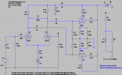
Is this what you mean Ballpencil?

It works great before connecting FB but when FB is connected with or without coupling capacitor it throws off the balance at the output tube grids but Distortion at the output is reduced.
Is this what you mean Ballpencil?
It works great before connecting FB but when FB is connected with or without coupling capacitor it throws off the balance at the output tube grids but Distortion at the output is reduced.
Attachments
If you are going to use the non-inverting triode's grid as the application point for NFB, you must use a CCS as the tail load. Forced symmetry is, most definitely, your "friend". LTP = long tailed pair and a resistor is not "long" enough, when NFB is in the picture.
Think of the CCS as being either the fulcrum of a "teeter/totter" or glue that binds everything together.
Think of the CCS as being either the fulcrum of a "teeter/totter" or glue that binds everything together.
C3 is no longer needed but it won't hurt.
470k:270k feedback ratio? That's excessive, isn't it? Maybe try R2 100k: R16 10k and work from there? I usually aim for feedback ratio that yields full output power at 2Vpp input. Eli's suggestion to use CCS is good. You can use pentode CCS if you want to keep it SS-free. Pentode CCS only needs 100-150v so that's another bonus.
470k:270k feedback ratio? That's excessive, isn't it? Maybe try R2 100k: R16 10k and work from there? I usually aim for feedback ratio that yields full output power at 2Vpp input. Eli's suggestion to use CCS is good. You can use pentode CCS if you want to keep it SS-free. Pentode CCS only needs 100-150v so that's another bonus.
My experience was that LTPs are bad for feedback connections as well as for being driven with balanced signals.
The best way to use a LTP is to drive it with a simple triode where you can inject feedback.
'saving one stage' will give you nothing, instead your gain will be insufficient for decent feedback.
LTP requires constant current sinks.
In my best amplifier I use a pentode at -180 V and the ECC99 at 15 ma, which is enough current to supply any power pentode like the KT120 and KT88 which I like equally.
If you are going to use the non-inverting triode's grid as the application point for NFB, you must use a CCS as the tail load. Forced symmetry is, most definitely, your "friend". LTP = long tailed pair and a resistor is not "long" enough, when NFB is in the picture......
Care to elaborate on this? I understand that a high tail resistance is generally good for LTP balance, but how and by what mechanism would insuffisient tail resistance influence the feedback loop?
Is this not the most common way of providing feedback in solid state amps? Again, seriously asking - what has changed between hollow- and solid state?My experience was that LTPs are bad for feedback connections as well as for being driven with balanced signals. ......
Care to elaborate on this? I understand that a high tail resistance is generally good for LTP balance, but how and by what mechanism would insuffisient tail resistance influence the feedback loop?
The ideal long tail is an infinite impedance at all frequencies. Under those circumstances, coupling at the cathodes is perfect. A constant current sink (CCS) is a fair approximation of infinity that achieves excellent cathode coupling. Quite a few designs employing resistive tails use unequal valued plate load resistors, to achieve AC balance. AFAIK, none of those designs apply NFB to the non-inverting triode's grid.
Eli,
Honest question, LTP is nothing more than a cathode follower coupled to a grounded grid amp. A grounded grid has low input impedance, let's say 1k. This 1k is the load that the cathode follower sees, right? 1k is way lower than the 51k tail resistor so i don't understand the benefit of a CCS in making a perfect cathode coupling as what the cathode follower sees is still low. Can you help to explain?
Honest question, LTP is nothing more than a cathode follower coupled to a grounded grid amp. A grounded grid has low input impedance, let's say 1k. This 1k is the load that the cathode follower sees, right? 1k is way lower than the 51k tail resistor so i don't understand the benefit of a CCS in making a perfect cathode coupling as what the cathode follower sees is still low. Can you help to explain?
A LTP is a differential gain block, which driven at only the inverting I/P. Check the reference libraries for the theory.
A CCS in the tail forces symmetry between the 2 sides. Current increasing on 1 side must be accompanied by current decreasing on the other. In the archives, you will find posts by SY dealing with his experiments on LTPs constructed from dissimilar triodes, with a CCS in the tail. Bottom line, the CCS forces symmetry between the 2 sides, even with dissimilar triodes.
A CCS in the tail forces symmetry between the 2 sides. Current increasing on 1 side must be accompanied by current decreasing on the other. In the archives, you will find posts by SY dealing with his experiments on LTPs constructed from dissimilar triodes, with a CCS in the tail. Bottom line, the CCS forces symmetry between the 2 sides, even with dissimilar triodes.
Of course! Thank you. The key is the constant total current between both sides. The grounded grid input impedance doesn't matter as long as the CCS keeps the total current fixed. This is not achievable with "short" tails.
AFAIK, none of those designs apply NFB to the non-inverting triode's grid.
Agreed. If we would apply FB to the non inverting input of a differential pair, it wouldn't be negative feedback at all, right?
OTOH, applying NFB to the common grid triode in a LTP is very common and seen in many designs.
Best regards!
Agreed. If we would apply FB to the non inverting input of a differential pair, it wouldn't be negative feedback at all, right?
OTOH, applying NFB to the common grid triode in a LTP is very common and seen in many designs.
Best regards!
It's negative feedback, if a portion of the O/P signal in phase with the signal applied to the inverting grid is applied to the non-inverting grid. Scan the archives for the "El Cheapo" schematic.
- Status
- Not open for further replies.
- Home
- Amplifiers
- Tubes / Valves
- Trying to get my bearings on LTP & feeling like a dummy