OK. Well those diodes are half drawn as LED's (with the arrow) and so it would make sense to have a 2v0 diode in place of an LED. That suggests it is used as a voltage reference.
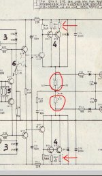
You still need to measure the bias current. I see there are two 0.22 ohms in the collector of the outputs (circled) as well as the ones I mentioned earlier (arrowed).
Measure the voltage across either 0.22 ohm circled and calculate the current. Do that for both channels.
Bias adjustment looks 'difficult' because Audiolab haven't provide a preset but instead have three parallel resistors where it is assumed that some combination of the three will give the required current range. Nice 😀
Attachments
My amp is the later 8000p, basically an 8200p the manual is available online here Google audiolab 8200p service manual I don't know if this helps, but it's different to the original 8000p in a few ways. There are variable resistors, pots for bias adjustment according to the service manual. Check it out mooly if you like and maybe you can help some more. Cheers having a whiskey while I post ��
So does your amp have the bias presets like the 8200 or are fixed resistors fitted ? If presets then its easy.
You still need to measure the current first though to get an idea of what is going on.
You still need to measure the current first though to get an idea of what is going on.
Back again. I replaced all the resistors and diodes, all is still ok. I took readings from R148 and R248, using the service manual for an 8200p which is basically the late 8000p that i have. Firstly i turned the amp on after turning on the 8000a with the settings both at CD, with volume down.
Taking a first reading from R148 and R248 and setting the bias to 65mv using a multimeter by way of variable resitors RV101 and RV201 (I think) after 15 minutes i set the value to 24mv at each resistor. After a further 30 minutes i set the value at each resistor to 22mv and it stayed at these values upon checking some time later.
I'm not sure if all is ok and the temperature of the amp at reasonably cool outside the casing, at the transistor to heatsink point it feels much warmer (about 50C) to touch. The sound from the amp sounds ballanced, clear and with no distortion that i noticed.
My question is, have i set the bias correctly for this amp and should it run lukewarm (outside case temp)
Does the service manual give a recommended current ?
Looking at the circuit and I would say those values sound high. The configuration of the output stage suggests a current nearer to 12ma per pair and so that would be around 5.3 millivolts across each of those 0.22 ohms that make up R148. You would see around 2.6 millivolts across each individual emitter resistor of the output pairs.
Looking at the circuit and I would say those values sound high. The configuration of the output stage suggests a current nearer to 12ma per pair and so that would be around 5.3 millivolts across each of those 0.22 ohms that make up R148. You would see around 2.6 millivolts across each individual emitter resistor of the output pairs.
Maybe this link will help Mooly http://www.hifi-studio.cz/pdf/Audiolab/Manualy/8200P-Audiolab service Manual.V01.2011.06.14..pdf this is the full manual that says mV DC final value at 22 mV DC Please take a look Mooly and see what you think 🙂
I read that as 22 mV across both resistors in R148/248, i.e. 11 mV across one or 50 mA. (So no surprise if things are running a bit hot at twice that.) That leaves 20 mA for each of the two output transistors when accounting for the 10 mA for the driver.
We're talking the big 2SC2922/2SA1216 here, so that's like 5 MHz fT at 20 mA... which actually still is surprisingly speedy for these chunky MT-200 beasts, Sanken's 10 amp jobs 2SC4468/2SA1695 aren't any faster. I wouldn't go much lower if I can help it.
We're talking the big 2SC2922/2SA1216 here, so that's like 5 MHz fT at 20 mA... which actually still is surprisingly speedy for these chunky MT-200 beasts, Sanken's 10 amp jobs 2SC4468/2SA1695 aren't any faster. I wouldn't go much lower if I can help it.
First time I've seen a full Audiolab manual. I read it the same as sgrossklass, 22mv across the combined total of the two 0.22 ohms. So 0.022/0.44 which is 50ma.
The procedure seems to show and imply that the bias stability vs temperature is not all that good. That could be a reason why it still seems overbiased to me. Based on what they outline as the procedure, when the amp is really hot (playing loud) then the bias could drop down to far and cause audible distortion.
All you can do is follow the recommended procedure for this one.
That seems like a good guess for the proportions through the output stage.
10mA through the drivers + 56r and 20mA through each output +0r22 for a total of 50mA.
I would expect the amplifier to still work pretty well with a much lower quiescent current.
Possibly as low as 26mA total, i.e. 10mA drivers and 8mA each output.
I would not expect cross over to become significant until the the outputs got to around 2 or 3 mA. (but this is a guess).
The amp runs pretty cool at up to the quarter volume, no distortion that i can hear. The manual that i have provided a link for is quite specific about the settings for biasing on page 15 from R148/248. The manual is an official audiolab service manual. The amp has 4 output transistors per side/ heatsink. I measured the voltage with a multimeter on DC mV with a final value of 22 mV DC so would this not be correct as it is the procedure outlined by audiolab. I'm asking the members here to help, but the answers i get are confusing and not really helping. Could someone put aside what they see in the diagrams, look at the procedure for biasing and let me know if i have set the bias correctly or am i missing something out?
1/ If you have followed the service manual procedure, then it is set up as per the manufacturers recommendation. That is the best you can do under the circumstances.
2/ The manufacturer as good as admits that the bias stability is poor by showing how the bias must be set to an initial value that is way over the final desired result. It should have been possible to design the circuit with better stability than that imo. They are relying on a set drift downward as the amp warms.
3/ The theoretical values for final bias would suggest a much lower value than Audiolab recommend. That is not practical based on how the bias varies so much with temperature. Run the amp really loud (so it gets very hot) and then re-measure the bias and then the evidence suggests it could then be way below the optimum. It could crash out to almost zero under those conditions.
So Audiolab are going for a compromise that is safe when cold, acceptable when at normal temperature, and not to low as to cause audible problems when its hot.
Thanks for that definitive answer Mooley. I understand you have a load of knowledge and I'm just starting out (have a lot to learn) it'll never be played beyond the 12 o'clock position as it would make my ears bleed. If you have a sweet spot that i should aim for Mooley by way of mV DC at R148/248 i could try that and see how it sounds, if not I'll leave it well alone and sit back and enjoy the results of my labour.
Thanks again
Thanks again
To satisfy your own curiosity you could try turning the bias all the way down (although it may not let you get down zero by design) and seeing how it sounds. If it does go to zero then you may detect distortion.
You could then set it for just one or two milliamps and see how the distortion vanishes.
Do the two transistors share the current equally. That's another can of worms 🙂 You can check that by measuring across the 0.22 ohms that are in each emitter of the power transistors. Voltages should be equal if they are sharing equally.
The 'sweet spot' would be somewhere around 11 to 12 ma per pair. So that is around 5 to 6mv across the combined 'dual' 0.22 ohm.
That last sentence should read 10 to 12 mv (because its a pair of output transistors).
10mv across 0.44 ohm is 22ma.
10mv across 0.44 ohm is 22ma.
I am very much in agreement with Mooly here.
But there is a possibility that Audiolab deliberately chose to have a temperature compensation behaviour as you have seen described in the manual.
A bias that start high when cold and reduces to a lower value when up to normal operating temperature is normally described as "over compensated".
This over compensation continues for a range above normal operating temperatures.
The effect of this is that if the amplifier ever overheats because one is reproducing excessive power for a domestic environment , or if one accidentally blocks the ventilation then the overcompensation further reduces the bias voltage/current and this reduces the heat load sent to the sinks. This prevents a blowup and reduces Warranty returns.
For all normal domestic use the amplifier is sufficiently biased to avoid (excessive) crossover distortion and it never blows up, = a good reputation that sells more amplifiers.
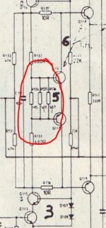
So just to make sure we're on the same boat, you are measuring directly on R148/248, right? These are dual resistors, with 3 legs.I measured the voltage with a multimeter on DC mV with a final value of 22 mV DC so would this not be correct as it is the procedure outlined by audiolab.
You should be reading, when warmed up:
EITHER
a) +/-22 mV across the two outer legs
OR
b) +/-11 mV between the middle leg and one of the outer ones.
If that is the case, the bias is set up correctly.
If you have 22 mV in case (b) (and accordingly, 44 mV in case (a)), it's set too high and should be corrected.
The rest of the discussion just revolves around how good the design is. There are some theoretically optimum values for biasing, which has received discussed here and e.g. in Douglas Self's Audio Power Amplifier Design Handbook. Self's value for a CFP output stage with 0.22 ohm emitter resistors is just 11.5 mA (5.06 mV), that would clearly never fly in this design which already runs the drivers at almost 10 mA, leaving less than 1 mA per output transistor - high-frequency crossover distortion would presumably be PA level rather than hi-fi.
It's becoming clear to me why NAD has CFP output stages using 0.068 ohm (no typo) resistors, and that's using just one pair of outputs. I guess we're up to ~20 mA at this point. So basically CFPs pretty much have to be run more or less overbiased to get enough current through the outputs.
Last edited:
All good at outer legs of R148/248 22mV DC and not from the middle + outer legs will leave it well alone at this cause it's stable at the levels i push it up to. Thanks for all the replies folks. Might mess around with it at a later stage!
- Status
- Not open for further replies.
- Home
- Amplifiers
- Solid State
- Audiolab 8000p and coffee