Hi,
I am trying to observe some DAC points on an oscilloscope.
It is a sigilent 200MHz scope.
Probe is correctly compensated and set at 1x.
CH1(yellow) is connected to the GND stub on the scope
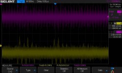
CH2(pink) is connected on the DAC XLR output (between pins2,1)
The DAC is powered on but there is no signal being fed to it.
The noise levels seem very high.
Am i doing to wrong? What could be the source of this crud?
thanks in advance for comments and help.
I apologize for the poor contrast in the image, but thats the image saved by the scope. Will need to investigate how to save better screenshots.
I am trying to observe some DAC points on an oscilloscope.
It is a sigilent 200MHz scope.
Probe is correctly compensated and set at 1x.
CH1(yellow) is connected to the GND stub on the scope
CH2(pink) is connected on the DAC XLR output (between pins2,1)
The DAC is powered on but there is no signal being fed to it.
The noise levels seem very high.
Am i doing to wrong? What could be the source of this crud?
thanks in advance for comments and help.
I apologize for the poor contrast in the image, but thats the image saved by the scope. Will need to investigate how to save better screenshots.
Attachments
Sorry. Meant to post this to the 'Equipment & Tools' forum, but in a hurry got it wrong.
Can one of the mods help move this.
thanks
Can one of the mods help move this.
thanks
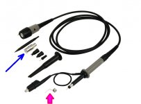
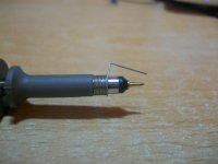
When I connect my scope probe tip to probe ground (crocodile clip), I see 10 millivolts of high frequency noise. The only way to make this disappear, on my scope anyway, is to use a better grounding scheme. Either the pigtail ground (red) or the BNC female adapter (blue) works well.
_
_
Attachments
I have never found scopes to be great tools for viewing low-level audio signals in the single digit millivolt range. First, the scope itself has a high noise floor (relative to audio work). Second, the scope is showing you all sorts of high frequency digital-related noise in the signal out of the audio band that you may not care about even if it is really there.
I have had some luck with adding a low pass filter and preamp as a front end to the scope. Better yet, use a USB sound interface and a PC (but still you have to mind grounding, balanced input, noise from USB, etc).
I have had some luck with adding a low pass filter and preamp as a front end to the scope. Better yet, use a USB sound interface and a PC (but still you have to mind grounding, balanced input, noise from USB, etc).
It looks like your DAC has some clock feedthrough and otherwise you are mainly measuring your scope's noise.
Last year I tried to measure the noise floor of a home-made DAC using a preamplifier, A-weighting filter and oscilloscope, but that didn't work out well either. It is a noise-shaping DAC and the out-of-band noise rises faster with frequency than the A-weighting filter rolls off. In fact I could switch the DAC between three noise-shaping algorithms and the algorithm that produced the least audible noise gave the largest signal on the scope. I then switched to using an audio recorder and an audio editing program.
Last year I tried to measure the noise floor of a home-made DAC using a preamplifier, A-weighting filter and oscilloscope, but that didn't work out well either. It is a noise-shaping DAC and the out-of-band noise rises faster with frequency than the A-weighting filter rolls off. In fact I could switch the DAC between three noise-shaping algorithms and the algorithm that produced the least audible noise gave the largest signal on the scope. I then switched to using an audio recorder and an audio editing program.
Thanks for all the comments and pointers.
The scope supports down to 500μV/div. So a noise floor significantly higher than that is a bit of a surprise for me.
I agree, a sound card analyzer is better for low level measurements.
I was investigating some gross audible issues from the DAC.
http://www.diyaudio.com/forums/digital-line-level/300403-hearing-strange-distortions.html
Can one of the moderators please move this to "Tools and Equipment". This is really out of place in multi-way loudspeakers.
thanks
i am seeing all kinds of noise and even some 60Hz components through the scope.
At this point, not sure what is from the circuit under test and whats from the scope/probe.
Is the scope input/probe that sensitive and unreliable for low level signals?
At this point, not sure what is from the circuit under test and whats from the scope/probe.
Is the scope input/probe that sensitive and unreliable for low level signals?
Can one of the moderators please move this to "Tools and Equipment". This is really out of place in multi-way loudspeakers.
thanks
At your service 🙂
George
Several issues. First a scope probe in X1 won't be low noise. The center conductor of the probe cable is resistance wire and pretty high resistance to work. (Its in the Tektronix probe introduction you can find somewhere on the web). Second the probe's shielding and resistance to ambient noise may be not be really high. There are reasons Tek and HP probes are so expensive. To check the scoped internal noise you need to shore the input. easy way is a 50 Ohm terminator on the input. The noise is s till broadband (DC to XX MHz) and every unit of bandwidth add noise. 20 MHz will have 1000X the noise of 20 KHz.
Finally I'm not sure why you are connecting the probes that way? If the output is single ended you would put the ground on pin 1 and probe pin 3 (or 2). For a differential output one probe connects to pin 3, the other to pin 2 and you subtract Ch1 from Ch 2 in the scope. I would use BNC cables instead of scope probes to get lower noise and better shielding.
To get a meaningful idea of the noise use the scope's FFT in log form so you can see the frequency bands of the noise and separate out the ultrasonic stuff from the audio band.
If you are trying to get a performance measurement of the DAC use a sound card and FFT software like ARTA or RMAA. You will need probably 140 dB plus dynamic range, something the limited bit depth of the scopes ADC's won't have.
Good luck.
Thanks Demian for the in depth comments.
I had tried some of the items you mentioned, like math mode subtract function to emulate differential input using the two channels and using scope FFT mode to look at the spectrum.
But your explanation of noise susceptibility of the scope inputs and probes in valuable.
But visualizing so much noise (albeit most of it ultrasonic) made me wonder how the DAC and amplifier electronics handle or react to them. I also wondered if there is any seriously elevated power line noise issues in my setup (again something hard to conclusively investigate without proper probes or jigs).
I have been trying REW, ARTA and an eval version of spectraplus with sound cards. Turns out that the the focusrite 2i2 i was initially using has elevated noise floor and is unsuitable for measuring the DAC. I had much better luck with my Motu 828mk3.
Also have a emu1212m, but no PCI slot PC 🙁
Couple of things my investigation helped me do was to reduce the gain on all the Hypex modules to allow them to be fed a better S/N from the DAC at nominal listening levels. This clearly helped. Also tried passive XLR attenuators which in fact even made the bass driver distortion disappear completely. Strange thing is i wasnt able to notice the audible distortions on my DAC output spectrum analysis. That made me wonder if the DAC out, AMP input combination is the real source of the distortion.
Cant yet view the Amp output directly on the soundcard, as i dont have the right attenuators. This is definitely on the list to try.
Finally i am also going to try out the EMC Neutrik connector to see if that is able to block out any HF noise that might be the causing the amp to behave funny and produce the audible buzz/crackle.
I will keep the thread posted as i find time to investigate.
Thanks for help.
Last edited:
But visualizing so much noise (albeit most of it ultrasonic) made me wonder how the DAC and amplifier electronics handle or react to them.
With due respect, I believe Demian's point was that the noise you see on your scope isn't DAC noise, but rather from the instrument/test probes. The DAC/amp doesn't need to handle what's not there.
Jan
With due respect, I believe Demian's point was that the noise you see on your scope isn't DAC noise, but rather from the instrument/test probes. The DAC/amp doesn't need to handle what's not there.
Jan
Jan, My apologies, I wasn't clear. I did understand Demian's point about the probe/scope.
I was just wondering how far the DAC output and amp inputs have noise immunity. I do believe they can be competently designed to be robust.
The DAC ouput noise is not in the range of what i'm seeing on the scope.
But soundcard readings showed
66dB SNR : 1KHz -20dB test tone, DAC volume setting 20dB (nominal listening)
THD+N: 0.047%
110.7 dB SNR: 1KHz -9dB test tone, DAC volume at full scale 0dB
THD+N: 0.00029%
I am still learning here, but these numbers dont seem bad at all from the DAC.
The distortion is likely in the DAC,AMP pairing. Some marginal stability issue?
Does that disappear due to the way the passive XLR attenuator i tried, loaded the DAC output? Not really sure, learning as i investigate.
Hence my desire to observe on a scope. At this point i think my best bet is to get the amp output into the sound card through right attenuation and repeat the spectrum analysis.
Hello,
Maybe the first think to do is to check if you measure same thing when you put the active oscilloscope probe tips directly on the ground (0V) (keeping the ground clips on it's place).
If as it's probable, you see mainly same thing, then you show common mode noise, not really noise coming from DAC itself.
I agree also with Demian that the best way would be to use directly a coaxial cable (not a probe) that
you can solder directly on the measurement point with shorter length as possible.
Frex
Regarding ultrasonic noise and amplifiers, the main thing is that the ultrasonic noise going from the DAC to the amplifier should not be large enough to make the amplifier go into slewing or anywhere near slewing. For a slow amplifier with bipolar input stage, no local feedback in the input stage and no input filter (very worst case), this means that the quasi-peak value of the noise has to be much less than kT/q ~= 26 mV, or much less than 2 kT/q ~= 52 mV for a differential pair input.
Hi Frex,
yeah i could try a coaxial BNC cable instead of the probe.
I tried the pigtail ground spring on the probe and measured directly at the DAC power supply's GND point. Will post the scope images
yeah i could try a coaxial BNC cable instead of the probe.
I tried the pigtail ground spring on the probe and measured directly at the DAC power supply's GND point. Will post the scope images
scope screen shots
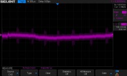
1. DAC powersupply GND with DAC unconnected to power cable
Some periodic spike can be seen
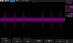
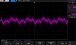
2. same point with DAC power cable connected and powered on
3. same point, different timescale: DAC powered on
Seems like ripple on the DAC dc powersupply
4. Probe held in my had without contact to anything
now what is that??
1. DAC powersupply GND with DAC unconnected to power cable
Some periodic spike can be seen
2. same point with DAC power cable connected and powered on
3. same point, different timescale: DAC powered on
Seems like ripple on the DAC dc powersupply
4. Probe held in my had without contact to anything
now what is that??
Attachments

Last edited:
- Status
- Not open for further replies.
- Home
- Design & Build
- Equipment & Tools
- DAC noise observation on Oscilloscope