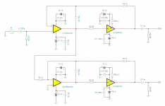
In his book Small Signal Audio Design (2nd Ed), Douglas Self describes an interesting way of creating a zero-impedance balanced output (p. 545, Figure 19.8b).
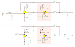
For my preamplifier, I'd like to use this design and to add LME49600 buffers so that this line driver can also directly drive my headphones without breaking a sweat (using relays to switch between the regular and the headphone output). The schematic below has the added buffers; would this be the right way to adapt his design? (The orange rectangles mark which parts have been added.) Or are there subtleties that I'm overlooking?

Also, Self writes that C4 and C8 (100pF ceramic capacitors, I assume C0G/NPO dielectric) are included for HF stability. Several composite amplifiers using the LME49600 do not seem to include these. Are they still needed here, given that my cables are very short? What are the pros and cons?
For my preamplifier, I'd like to use this design and to add LME49600 buffers so that this line driver can also directly drive my headphones without breaking a sweat (using relays to switch between the regular and the headphone output). The schematic below has the added buffers; would this be the right way to adapt his design? (The orange rectangles mark which parts have been added.) Or are there subtleties that I'm overlooking?

Also, Self writes that C4 and C8 (100pF ceramic capacitors, I assume C0G/NPO dielectric) are included for HF stability. Several composite amplifiers using the LME49600 do not seem to include these. Are they still needed here, given that my cables are very short? What are the pros and cons?
R4, R8 would go in front of the buffer.
As it happens, I just wrote something on this over here.
So you have headphones wired balanced? What does "very short" mean? Non-negligible capacitance could mean more than 100-200 pF, and I've measured 3m long Sennheiser cables to be on the order of 1 nF. I certainly wouldn't appreciate having a headphone cable that's only about 1 m long for stationary listening. (And TBH the mechanical aspects would be >> the electrical ones. Headphone cables are all about weight, stiffness and microphonics first, electrically they only have to be good enough for the job.)
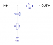
It wouldn't hurt to include a Zobel as well, and maybe a few ohms of output resistance (or R || L) depending on how critical your cans are.
BTW, that rail decoupling looks a bit skimpy. Try more like 10 µF on the OPA and at least 100 µF on the buffer. Keep ground return impedance low... but that I also discussed over there.
Last edited:
Thanks, I've updated the schematic accordingly.R4, R8 would go in front of the buffer.

The headphone cable is indeed a few meters. The interconnects between the preamp and the power amp are about 30cm each.As it happens, I just wrote something on this over here.
So you have headphones wired balanced? What does "very short" mean? Non-negligible capacitance could mean more than 100-200 pF, and I've measured 3m long Sennheiser cables to be on the order of 1 nF. I certainly wouldn't appreciate having a headphone cable that's only about 1 m long for stationary listening.
It wouldn't hurt to include a Zobel as well, and maybe a few ohms of output resistance (or R || L) depending on how critical your cans are.
Like this? I reckon I'll need to do this for the hot as well as the cold output?

Good point, I haven't really settled on the decoupling yet. I was indeed thinking of using an RC filter for the rails like you mentioned in the other thread, although I'm not sure what a suitable resistance would be here. Something like 10 Ohm with a 10 uF ceramic capacitor for decoupling would have a cut-off frequency of about 1.6 kHz.BTW, that rail decoupling looks a bit skimpy. Try more like 10 µF on the OPA and at least 100 µF on the buffer. Keep ground return impedance low... but that I also discussed over there.
In theory the Zobel could also go between the hot and cold outputs (with half the R and double the C) though I have no idea whether that's a good idea in practice. Depends on how well the inversion works at critical freqs of 1 to several MHz, I guess. (Speaking of which, I'd say the 1k input resistor of the inverter better goes on the buffered output of the noninverting part.)Like this? I reckon I'll need to do this for the hot as well as the cold output?
View attachment 604460
For the output series resistor, try something around 5 ohms. That's low enough even for the pickier fullsize headphones, though BA IEMs may still object. If you feel the need to accomodate these, you can always go for a parallel RL, though finding some good suitable chokes is another matter. (You can always go with the usual 10-20 turns air core wound around an AA battery if that's not too chunky for your tastes.)
That sounds a bit high. You've got something like a +/-15 V supply, right? Assuming you've got the space, you could give the buffer 10 ohms and 470µ || 10µ (tantalum / ceramic), the opamp maybe 220 ohms and 22 µF.Good point, I haven't really settled on the decoupling yet. I was indeed thinking of using an RC filter for the rails like you mentioned in the other thread, although I'm not sure what a suitable resistance would be here. Something like 10 Ohm with a 10 uF ceramic capacitor for decoupling would have a cut-off frequency of about 1.6 kHz.
If you haven't decided on regulators yet, I'd say an LM3x7 pair in a low-noise config with a decent amount of capacitance on the output (220-470µ) plus protection diodes should be quite adequate, certainly so with all this filtering going on (assuming it's done in a similar manner elsewhere). It's advisable to do the math on expected quiescent currents, with these it's not a bad idea to have at least 30 mA going through them. (The usual crux of series regs - open-loop output impedance is always a function of pass transistor current and beta, and so is closed-loop output impedance.)
If you do not depend on supplies being some exact value, you can also consider just running some cap multipliers, which could be used to reduce dissipation in that area if unregulated supplies are reasonably clean to begin with. It is also possible to modify a cap multiplier with multistage (RCRC) filtering to include a zener so that maximum voltage output is limited to a safe value even at excessive line voltage. Decisions, decisions...
Last edited:
That makes sense, thanks for pointing it out.(Speaking of which, I'd say the 1k input resistor of the inverter better goes on the buffered output of the noninverting part.)
I'll adjust it to 5 Ohms. For stationary listening I only use big over-ears, so IEMs do not factor into the equation here. 🙂For the output series resistor, try something around 5 ohms. That's low enough even for the pickier fullsize headphones, though BA IEMs may still object.
That's exactly what I did for the power amp; the inductance was something like 2µH.You can always go with the usual 10-20 turns air core wound around an AA battery if that's not too chunky for your tastes.
Sounds good. Does it matter for the large cap (470µF) on which side of the resistor it's placed?That sounds a bit high. You've got something like a +/-15 V supply, right? Assuming you've got the space, you could give the buffer 10 ohms and 470µ || 10µ (tantalum / ceramic), the opamp maybe 220 ohms and 22 µF.
For the OPA1612 op amp, should I also put a smaller X7R cap in parallel with the 22µF one? I noticed the datasheet and example designs from TI typically have 0.1µF MLCCs in place as well. Perhaps that's more important for high-speed applications though.
I've been itching to try a bipolar PSU using Mean Well SPS modules. It's got a CLC filter that reduces noise to a few mVrms. If that's still too noisy for this application I could always follow it up with a low-noise linear reg (I've left some pads for a LT3081).If you haven't decided on regulators yet, I'd say an LM3x7 pair in a low-noise config with a decent amount of capacitance on the output (220-470µ) plus protection diodes should be quite adequate, certainly so with all this filtering going on (assuming it's done in a similar manner elsewhere). It's advisable to do the math on expected quiescent currents, with these it's not a bad idea to have at least 30 mA going through them. (The usual crux of series regs - open-loop output impedance is always a function of pass transistor current and beta, and so is closed-loop output impedance.)
😀Decisions, decisions...
Buffer side, of course.Sounds good. Does it matter for the large cap (470µF) on which side of the resistor it's placed?
You'd probably get along without one if the 22µ is decently low ESR, but yeah, maybe at least a 100n across the rails.For the OPA1612 op amp, should I also put a smaller X7R cap in parallel with the 22µF one?
Ugh, evil SMPS.I've been itching to try a bipolar PSU using Mean Well SPS modules.

What was the big advantage of using these in an application like this again...?
I would plan on using an IEC socket with proper integrated mains filter and whack some common-mode chokes into the module outputs. Is the unit going to be Class I or Class II? (If you're all-balanced, Class I is just fine, any kind of unbalanced connections potentially are not going to be fun though. Class II with SMPS tends to be a mess, usually far too much coupling across the transformer, unless it's one with a shield winding.)
Millivolts? I was talking something like 30 µVrms @ 20k BW. Even a 78M series reg would usually be at about 75 µV (78xx/79xx are often noisier at 200-300 µV), and that's certainly not unwarranted.It's got a CLC filter that reduces noise to a few mVrms.
RC filtering would obviously take a lot of the noise out (and largely keep the ground returns from being polluted), but that would also be direly necessary. Some more CLC before that may be useful.
Sounds good. Plus LT3091 for the negative, I guess?If that's still too noisy for this application I could always follow it up with a low-noise linear reg (I've left some pads for a LT3081).
You may still be able to take some hints from the guru:
https://www.youtube.com/watch?v=WxhjLIu-vPg
Fair enough, it doesn't make a whole lot of sense here given the power draw of a typical preamp. Still, I like how compact these supplies can be, even with the added filtering.Ugh, evil SMPS.
What was the big advantage of using these in an application like this again...?
Class I for sure; Class II is a little too tricky for me for now. Maybe when I'm a few more years into this hobby. All connections to external equipment are balanced.I would plan on using an IEC socket with proper integrated mains filter and whack some common-mode chokes into the module outputs. Is the unit going to be Class I or Class II? (If you're all-balanced, Class I is just fine, any kind of unbalanced connections potentially are not going to be fun though. Class II with SMPS tends to be a mess, usually far too much coupling across the transformer, unless it's one with a shield winding.)
Spot on. In the past I've also created a bipolar PSU from 2 LT3083 regulators, but using a dedicated negative reg is probably a better idea. For some reason the specified noise from the negative regulator is a tad bit lower at 18μVRMS vsPlus LT3091 for the negative, I guess?
27μVRMS from the positive one.
Really informative, thanks for the link!You may still be able to take some hints from the guru:
https://www.youtube.com/watch?v=WxhjLIu-vPg
- Status
- Not open for further replies.
- Home
- Source & Line
- Analog Line Level
- Adding a buffer to Self's zero-impedance balanced output