Sorry for my bad english, I already search this forum but I can't find a solution, so I decide to create new thread.
Hello I'm Ayok, I build some analog vu meter with a simple circuit from google, it just diode rectifier to 4.7 cap, then a trim pot to the vu display.
I wired that in to my stereo out from my m-audio fast track, but there's very minimal movement,
Then I decide to wired it to headphone output, it a bit better signal than stereo out, but I'm still cannot calibrate to -18 dbfs
Am I do wrong? Or I need some power for boost signal to the Vu?
Best Regards,
Hello Ayokzone,
with that simple circuit you get only meter movement at the loudspeaker output of an amp.
If you require signal measurement at line level you need a active circuit to drive the VU meter.
Examples of that are in the previous reply.
with that simple circuit you get only meter movement at the loudspeaker output of an amp.
If you require signal measurement at line level you need a active circuit to drive the VU meter.
Examples of that are in the previous reply.
Can you please give us more information about your "VU display". What kind is it?
THANKS
Hi Stella, for the passive board I use this schematic, but it did not work 😡 then I try to make active board.
An externally hosted image should be here but it was not working when we last tested it.
Hello Ayokzone,
with that simple circuit you get only meter movement at the loudspeaker output of an amp.
If you require signal measurement at line level you need a active circuit to drive the VU meter.
Examples of that are in the previous reply.
Thanks for your replies 😀 because I'm newbie at DIY circuit I decide to use this schematic for active VU

It does work and can be calibrated with DAW, but when I compare with Klanghem VU in my Studio One, it moves diferrent, looks like the DIY VU not respons at low frequency, I'm confused what's wrong, or maybe because my circuit it's to simple

Use one of these ics: TA7318P (40dB dynamic) or TA7332P (20dB dynamic), a simple circuit can be found googling in the net.
How much I supossed upgrade it? or anything above that value?You could try increasing the value of C4
Okay. I'll try to rebuild it, thanks sir> I decide to use this schematic for active VU
That has significant flaws. The level trimmer messes-up the transistor bias. The input capacitor has wrong polarity.
I know that, but I'n my country theres a very expensive shiping cost, 😡Use one of these ics: TA7318P (40dB dynamic) or TA7332P (20dB dynamic), a simple circuit can be found googling in the net.
I think you should take PRR's advice first and see how you get on. Or search on the web and use a simple op amp based circuit
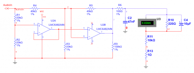
If you can get your hands on a rail-rail, low input bias current op amp, this precision full wave rectifier is accurate down to some tens of mV. The one shown is ~$1.60 in single quantity. I am sure that there are less expensive ones.
R6 and C1 are suggest values (hat tip ESP) for proper VU ballistics.
The VU panel meters from China are usually 100uA or 200uA full scale, so R10 is a shunt.
R6 and C1 are suggest values (hat tip ESP) for proper VU ballistics.
The VU panel meters from China are usually 100uA or 200uA full scale, so R10 is a shunt.
Attachments
- Status
- Not open for further replies.
- Home
- Source & Line
- Analogue Source
- DIY Analog VU Not Working