Gentlemen,
Before the dual supply version was around, I remember Mr. Hood himself
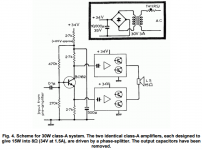
commenting on bridging the 69 version, both increasing the power output
and eliminating the output capacitors.
Selim
A link for more on this is here http://www.keith-snook.info/wireles...fier and Modular Pre-amp J L Linsley Hood.pdf
I couldn't open the appropriate article (I assume you meant Wireless World, July 1970) in Keith Snook's library but I did find Hood's proposed bridged mode design on page 4 here: http://sound-au.com/tcaas/jlh1970.pdfA link for more on this is here http://www.keith-snook.info/wireles...fier and Modular Pre-amp J L Linsley Hood.pdf
For anyone who isn't aware, you must rate each amplifier in a bridged mode design such that at full power, they can drive a load that is half of the loudspeaker's nominal impedance. i.e. an 8Ω speaker should be considered as a 4Ω load for each amplifier. There is no free lunch in audio and as you might expect, this means doubling the bias current and much larger heatsinks to cope with the overall quadrupling of heat emission too. I'm not sure bridging class A designs is such a good idea with today's typical 6Ω drivers.
Last edited:
I couldn't open the appropriate article (I assume you meant Wirless World, July 1970) in Keith Snook's library but I did find Hood's proposed bridged mode design on page 4 here: http://sound-au.com/tcaas/jlh1970.pdf
For anyone who isn't aware, you must rate each amplifier in a bridged mode design such that at full power, they can drive a load that is half of the loudspeaker's nominal impedance. i.e. an 8Ω speaker should be considered as a 4Ω load for each amplifier. There is no free lunch in audio and as you might expect, this means doubling the bias current and much larger heatsinks to cope with the overall quadrupling of heat emission too. I'm not sure bridging class A designs is such a good idea with today's typical 6Ω drivers.
Hello Ian,
I clicked on the link in the email notifying me of your post and had no trouble in opening the document which originates from the December 1970 issue. The Wireless World July 1970 Class AB circuit might be a slightly better candidate although the driver transistor is single-ended.
There are additional components to make that amplifier stable enough to drive electrostatic speakers. The hardware would be less bulky and less expensive to build.
Sorry, the above reference I posted should read December 1970 issue and I think the problem was with Microsoft's Windows 10 PDF reader. I just now installed Adobe's reader and it opens the file without a problem. So much for Microsoft's versions of proven, independent software.
Since the original article was from 1969, it may be that JLH was referring to bridging to feed a 16ohms speaker.
The Dec 1970 article showed this snippet as an idea. It may never have been built or proven but as you suggest Andrew, a 15Ω speaker was certainly part of the plan, allowing a normal (8Ω) level of bias to be used . That would have been a sensible arrangement in 1970 but unfortunately, the days when 15Ω speakers were an option have long gone.
Attachments
Hi folks. I recently listened to the amp simulations in Mooly's virtual listening room. I know nothing of the limitations of this kind of exercise, but for me, the JLH simulation sounded the best. I would like to build a couple, most likely, something very close to the original. Any suggestions/pointers would be very welcome indeed. Thanks
Last edited:
I recommend using modern linear gain transistors such as MJL3281A.They have high a gain (not necessarily higher than the original MJ481's) but the linear gain will reduce distortion and they give a better frequency response.
In my set-up I needed 33pF capacitors to stabilise, wired in parallel with the feedback resistor. You may need a small Rc-LR ("Zobel" network) in the output to stabilise against RF pickup or capacitive loading in the speaker leads.
You will almost certainly have to set the quiescent current up by trial and error. I would start by using a 1k driver load (no bootstrap) just to measure the quiescent current, then determine what load resistor to use for a current of approx. 1A (30V supply), which, having a linear gain, will be very nearly linear proportional. Then divide into two and connect the tap to the bootstrap capacitor.
Finally I would use larger bootstrap and output capacitors for a better bass response.
Last edited:
Thanks John, that's exactly the kind of starting points I need. Are there any pros or cons to using bipolar caps such as nichicon muse? Just to give you and idea of my set up, speakers are Jordan Eikona in VTL cabinet, and one of the things that attracts me to the JHL is the simple minimalist approach as presently I have home built mosfet amps based on the LME49830 chip and fancy a complete change and contrast.
Last edited:
Member
Joined 2009
Paid Member
I recommend using modern linear gain transistors such as MJL3281A.
I received similar advice. I stuck with some old 2N3055H (8 pairs for one channel) as I had them on hand. I have not been impressed by the sound as much as others write about so it's possible I'm not getting the best out of this amp with old transistors. So I'll add my 'yes' vote to trying a modern device for this simple amplifier.
I received similar advice. I stuck with some old 2N3055H (8 pairs for one channel) as I had them on hand. I have not been impressed by the sound as much as others write about so it's possible I'm not getting the best out of this amp with old transistors. So I'll add my 'yes' vote to trying a modern device for this simple amplifier.
Hi there ,too many newer 2n3055 out there and they are way out different then the NOS versions of the 70s.I do own a NAD3020 from 1978 and was able to check this excellent sounding 2n3055 devices with the current stock.It seems their characteristics are remarkably different in terms of Hfe and characteristics curves .I`m very skeptical on the current 2n3055 devices.
Hi folks. I recently listened to the amp simulations in Mooly's virtual listening room. I know nothing of the limitations of this kind of exercise, but for me, the JLH simulation sounded the best. I would like to build a couple, most likely, something very close to the original. Any suggestions/pointers would be very welcome indeed. Thanks
For anyone interested the files are still available:
http://www.diyaudio.com/forums/lounge/303727-welcome-virtual-listening-room.html
As to old and new transistors. What I can say is that simulated versions of the JLH69 using up to date modern transistor models always seem to give a quiescent current way below Johns stated values requiring R1 and R2 to be lowered to suit. I don't know if you are finding that with real builds or not that use modern devices.
Scottjoplin - I do not see enough information on the datasheet to know if MUSE caps are any better. My general approach is that unless you are operating them at zero bias or A.C. then D.C. polarised caps are fine. But check the impedance:frequency response, not just 100 or 120Hz data. You would have thought that a company selling "audio" capacitors would provide data relating to audio frequencies.
One reason for using larger capacitors is that the A.C. voltage across them will be smaller at a given frequency, hence less likely to cause distortion.
I have not specifically checked capacitors for distortion but there was a series of articles in Electronics World by Cyril Bateman and since then several Web pages covering various capacitor types. However using standard polarised caps did not appreciably increase the distortion of my JLH test amplifier- distortion measured was in line with expectations.
Member
Joined 2009
Paid Member
Are there any pros or cons to using bipolar caps such as nichicon muse?
I like these caps and have generally liked the sound of amplifiers that have used them although I haven't done controlled listening tests. For my JLH [ http://www.diyaudio.com/forums/solid-state/268846-tgm9-my-version-jlh-69-class-amplifier.html ] the idea was to use the MUSE caps in the power supply, nearest the output stage of the amplifier and to use plenty of them.
Thanks John and Bigun, I've read what Doug Self has to say about electrolytics and his references to Cyril Bateman's work, very interesting. Doug uses the polarised quite happily, but in his designs I have seen other people using non polarised, specifically MUSE, so, it just got me to wondering. Presumably it would be fine to parallel them on the output? I think they only go up to 1000uF
I think the operating voltage is only 16V, might be 25, so you would need to parallel several and then connect in series too. Maybe some on DIYAudio have compared these caps with other types, but I have not found reason to use anything other than standard.
You will need a ripple current of at least 1A - again I do not recall what the specs. were if you want to use them in the output capacitor position. I tend to use high current rated computer grade caps for this but even using some old Daly capacitors (when the UK used to make such things) I measured <0.02% distortion in a 50W amp.
You will need a ripple current of at least 1A - again I do not recall what the specs. were if you want to use them in the output capacitor position. I tend to use high current rated computer grade caps for this but even using some old Daly capacitors (when the UK used to make such things) I measured <0.02% distortion in a 50W amp.
Thanks for that, thought it was probably unnecessary, my aim with this one is simplicity, had enough complexity for a bit....not easy though this letting go..to 'quote' chrisb's signature. 🙂
Member
Joined 2009
Paid Member
Thanks John and Bigun, I've read what Doug Self has to say about electrolytics and his references to Cyril Bateman's work, very interesting. Doug uses the polarised quite happily, but in his designs I have seen other people using non polarised, specifically MUSE, so, it just got me to wondering. Presumably it would be fine to parallel them on the output? I think they only go up to 1000uF
The non-polarized MUSE are great for input caps and feedback shunt caps where there may not be much dc voltage across the cap at all. I've used them in several of my amps and have been very pleased with the results. In contrast, I have not been happy with film caps - I keep reading about why they are so good etc. but I've tried them in SS amps and in tube amps and the sound is often 'wrong'. The non-polarized MUSE caps sound neutral to my ears.
But for power supply rails with lots of dc voltage present I use polarized caps. You can certainly parallel as many MUSE caps as you like but be careful about creating a large load for the rectifier diodes and mains fuse when you first switch it on.
I can see this is going to be an interesting project for me. I've never built a class A amp before and the challenges are very different to AB. Luckily most off the time I listen at 'normal' levels, if not low, so the power issues are not a problem. The fact that the power supply is so much a part of class A is also quite new to me. I listen mostly to 40's to 60's jazz and I love the purity of some of those recordings. Ok, cd remasters, umpteen op amps and all that jazz(ha), but low level signal processing is vastly different to higher level, or so I understand? Perhaps the synergy off listening to those simple recordings through a simple amp would be...well...nice. Hope that doesn't all sound too daft.
I've been experimenting with a build of this amp for guitar practice which is currently outputting about a 1/2 Watt into 8 ohms.
What advice could anyone offer for the simplest way to add a headphone output to this?
I was hoping for something along the lines of very simple attenuation to reduce the output signal and a switching socket to swap from 'speaker out' to 'headphones out'.
Any advice? Thanks in advance!
What advice could anyone offer for the simplest way to add a headphone output to this?
I was hoping for something along the lines of very simple attenuation to reduce the output signal and a switching socket to swap from 'speaker out' to 'headphones out'.
Any advice? Thanks in advance!
- Home
- Amplifiers
- Solid State
- JLH 10 Watt class A amplifier