I added a soft foam strip to the brow band for more comfort. The lenses are actually pretty good and most work I use the lower 3x magnification. I use them for through hole soldering as well - eyes getting old. 🙂
My head-mount magnifier arrived a few days ago. I just had a chance to try it out - fantastic! Wow. These would be worth 5x the price. I agree, the lowest magnification set of lenses is probably what I'll use the most, but the flip-down set works well for a close-up of SMD pins.
I must have a large head. I had to rotate the band adjustment wheel nearly all the way out. 😛
Thanks for the suggestion! 🙂
Glad the magnifier worked out. Pretty fantastic deal and a life changer as far as giving me ability to solder tiny circuits. The lenses are indeed good because I wear them 3 or 4 hrs straight sometimes without a headache. The flip down lens is also good for reading SMT part numbers.
Hi Agdr,
I just finished assembling the amp with the new OPA1688 you provided me. I am still waiting for the 9v battery terminals to come in but in mean time using 0.100in pitch header pins and some 9v (nnon-alkaline cells mesuring 8.25v (used)). I measure voltage at the pins on the solder side but nothing turns on. Voltage at test points on left side is zero. Can you help me to debug or is this a case of batteries too weak and SSR's are shut off to protect headphones? Here are photos of top side and backside to help.
Thanks,
X
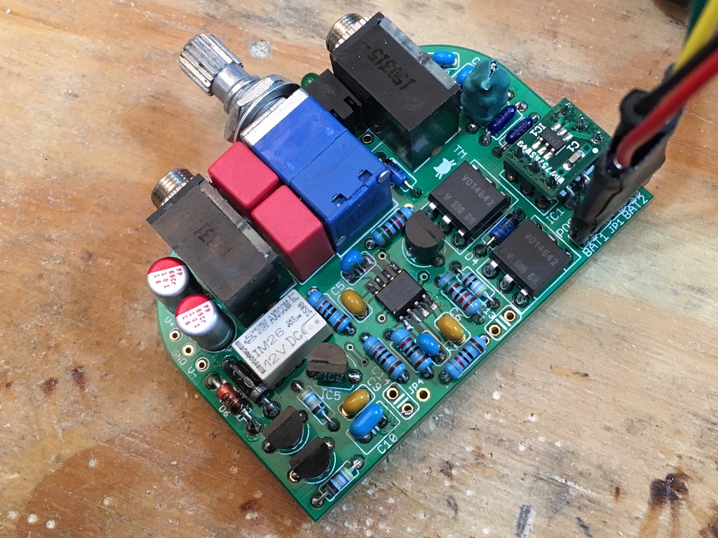
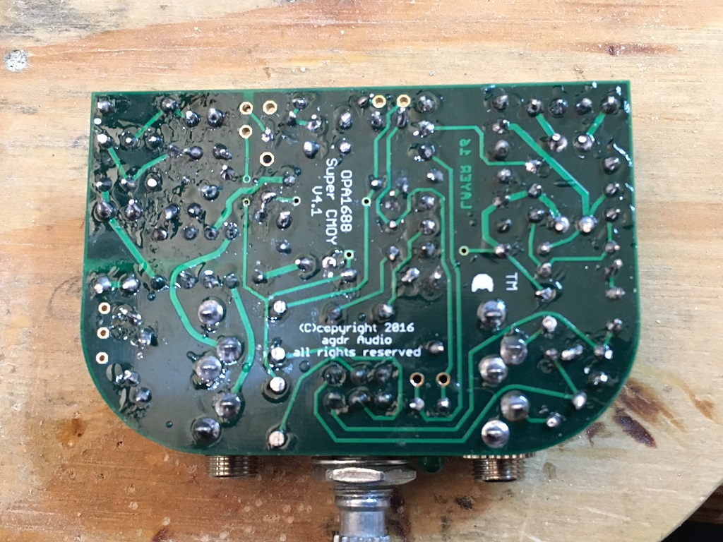
Attachments

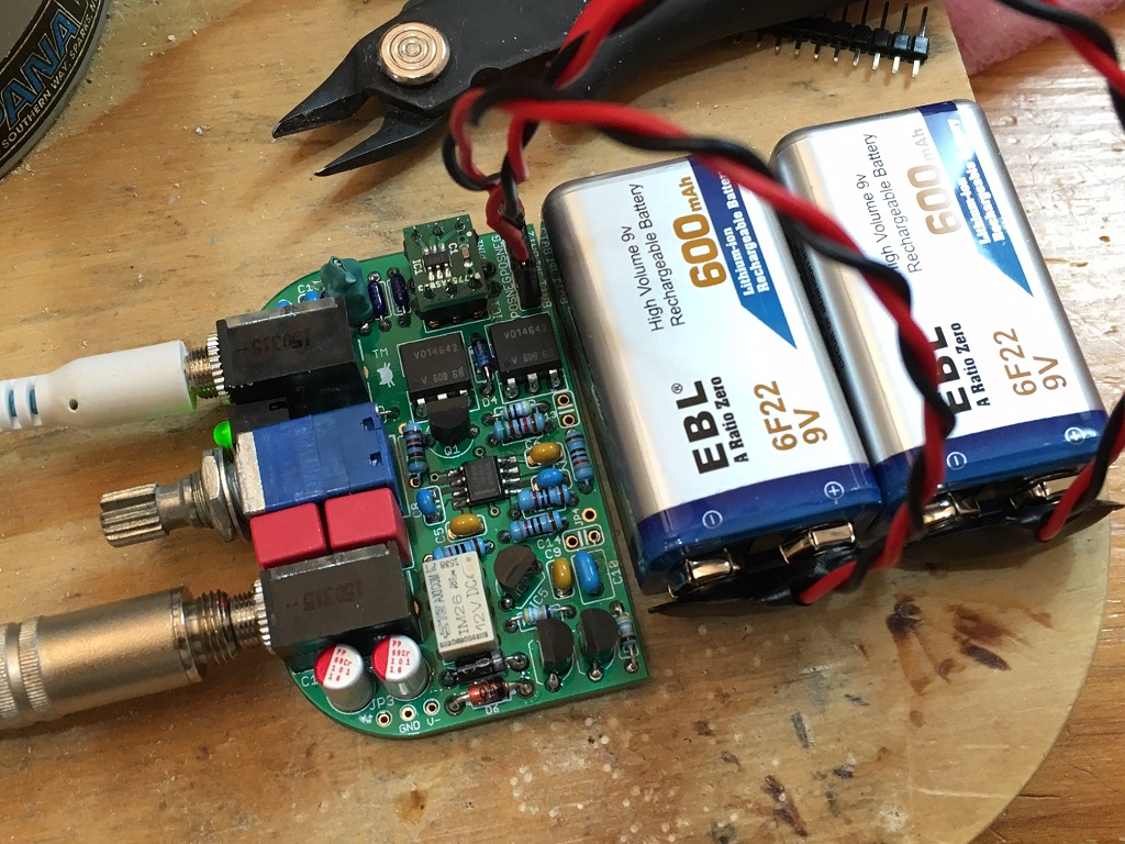
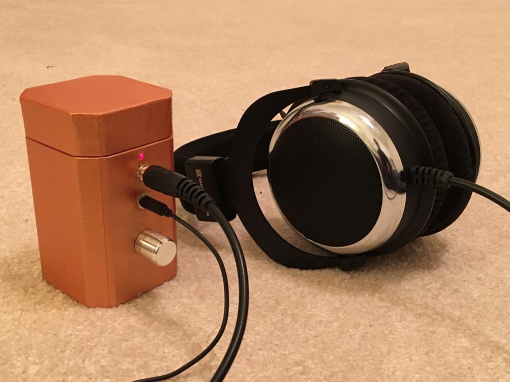
The amp works - I got the Li-ion 9v hooked up with proper connectors and it seems like the jacks need to be plugged in for the LED to come on? Listening to first song now. Very nice - just about the perfect gain at 2x for my DT880-250's.
Let me burn it in and listen to some more songs and I will give a report how it compares to my class A head amps.
Thanks Agdr for a nice compact mp design. 🙂
Let me burn it in and listen to some more songs and I will give a report how it compares to my class A head amps.
Thanks Agdr for a nice compact mp design. 🙂
Attachments

Congrats!
On my Super Cmoys the led comes on without anything plugged in....AGDR will chime in I am sure, but check all your work again, for proper orientation, shorts etc..
Alex
On my Super Cmoys the led comes on without anything plugged in....AGDR will chime in I am sure, but check all your work again, for proper orientation, shorts etc..
Alex
The amp works - I got the Li-ion 9v hooked up with proper connectors and it seems like the jacks need to be plugged in for the LED to come on? Listening to first song now. Very nice - just about the perfect gain at 2x for my DT880-250's.
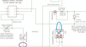
Congratulations on your build! 🙂 Sorry about the delayed reply, I'm just now getting back to the computer. The symptoms you were having at first are what happens if the tiny comparator chip on the little PC board doesn't turn on. If it were still dead I would have had you measure voltage at the points in the first two diagrams below. That part of the circuit is referenced to the negative power rail rather than ground, so your negative meter lead would go were the purple circle is (one end of R5) and the red lead where the blue circle is. When the comparator turns on that blue circled point is brought down to the negative rail, and then all the stuff in the series string turns on. Both SSR internal LEDs, the front panel LED, and the current source.
With the batteries connected (charged up, of course), the front panel LED should light any time the switch on the volume control is on. When you rotate the control all the way counter-clockwise and turn off the switch the front panel LED should go out.
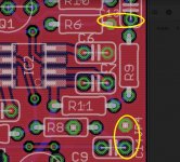
I see one problem though, in looking at the photo of your PC board. 🙂 For a gain of 2x there are two jumpers (just pieces of wire, cut-off resistor leads works fine) that have to be installed where the yellow circles are in the 3rd picture. As you have it right now you are getting a voltage gain of 1x, but it should have the capacitors installed differently for 1x to give you good phase margin for capacitive loads.
SO... first thing to decide is if it is loud enough as you have it right now, or if you need it twice as loud. Sounds like 1x here is working fine for you, which doesn't surprise me given the high sensitivity of your headphones. If you do want 2x gain then install those jumpers in the yellow circles and it will become twice as loud. That upper jumper goes from the hole where C13 would have been to the installed lead of R6 next to it.
If however you like the 1x gain you have now, you first need to remove C7 and C8, those blue 47pf capacitors. They are only used for gains greater than 1x. You can unsolder them just by heating the lead on one end and pulling the part up on that end, then the other end. Or you could take your flush cutters and cut the part off at the leads. 🙂 Then once C7 and C8 are out you would need to install C13 and C14, two 1nF capacitors. I think we included those with yours in case you decided on 1x gain, but I can't remember. If not just let me know and I'll send you a couple. And that is it! Once those capacitors are in you are done. The purpose of the capacitor change is to prevent any chance of oscillation with typical headphone loads.
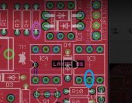
Hey one question, I see something green where R3 is at, near the back of the input jack, between the jack and the edge of the board. I just noticed that R3 and R4 are resistors that Digikey doesn't have. I'm guessing you put two in series there to try to make the 2.7 meg. It is important those resistors (R3, R4, and R5) be exact. If they are off by just a little bit it will mess up where the comparator turns on and off. That could be part of the trouble you were having. I have all those resistors here. I can send you two if you don't have the correct values in there, the 2.7 meg and 332K, both should be 1% tolerance or better.
Attachments
Last edited:
Hi Agdr,
Thanks for the tips. I just got it boxed up and it's working fine when powered from a DAC but could use more gain when fed by my iPhone. So I think I would like those jumpers. Funny thing is that thought 2x was not enough so I installed smaller R8 and R9 values (330R since I did not have 412R) and of course, there is no difference. I guess I will just install the jumpers and see if it is now too loud (maybe 4.5x?). The amp sounds really nice - surprisingly powerful and clear little package.
I actually used 4 resistors in series to get exactly 2.7Mohm and 330k instead of 332k - hope that is close enough for the comparator. I think it did not turn on before due to old batteries or a loose connection between the battery and the PCB at the header strip connector I installed. Seems ok now and turns on,
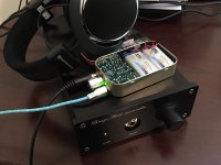
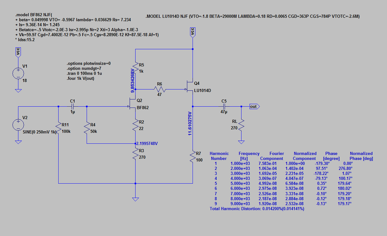
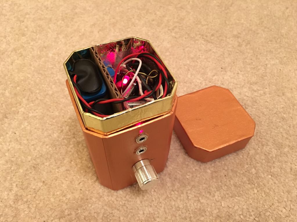
Here is the amp sitting on top of my single ended Class A dual JFET amp (yes, just two transistors in the amp!). This amp is currently my reference amp as it has a very clear sound, is super quiet, and has a very powerful and articulate bass. More info on this amp here:
http://www.diyaudio.com/forums/solid-state/301164-mosfet-source-follower-headamp-18.html#post4936115

So I am listening and comparing back and forth between the two amps to get a feel for the differences in sound. So far, the little Super CMOY is sounding very nice in the mids and highs, but the bass of the SE Class A amp is very clearly better. Not surprising given the huge low ESR cap bank, cap multiplier, and output pwer JFETs with 3mOhm Rdson. I will give more listening impressions later but the bass is clearly different.
I will go add those jumpers now.
Thanks,
X
Thanks for the tips. I just got it boxed up and it's working fine when powered from a DAC but could use more gain when fed by my iPhone. So I think I would like those jumpers. Funny thing is that thought 2x was not enough so I installed smaller R8 and R9 values (330R since I did not have 412R) and of course, there is no difference. I guess I will just install the jumpers and see if it is now too loud (maybe 4.5x?). The amp sounds really nice - surprisingly powerful and clear little package.
I actually used 4 resistors in series to get exactly 2.7Mohm and 330k instead of 332k - hope that is close enough for the comparator. I think it did not turn on before due to old batteries or a loose connection between the battery and the PCB at the header strip connector I installed. Seems ok now and turns on,
Here is the amp sitting on top of my single ended Class A dual JFET amp (yes, just two transistors in the amp!). This amp is currently my reference amp as it has a very clear sound, is super quiet, and has a very powerful and articulate bass. More info on this amp here:
http://www.diyaudio.com/forums/solid-state/301164-mosfet-source-follower-headamp-18.html#post4936115
So I am listening and comparing back and forth between the two amps to get a feel for the differences in sound. So far, the little Super CMOY is sounding very nice in the mids and highs, but the bass of the SE Class A amp is very clearly better. Not surprising given the huge low ESR cap bank, cap multiplier, and output pwer JFETs with 3mOhm Rdson. I will give more listening impressions later but the bass is clearly different.
I will go add those jumpers now.
Thanks,
X
Attachments
Last edited:
xrk971 - sounds good. yep if you need more gain do go ahead and add the jumpers. If you used 825R for R11 and R12 you would get a gain of (1 + 825/330) = 3.5x. Right now without the two jumpers installed R8 and R9 are not doing anything. So yeah that might suddenly become to much gain. If so replace R8 and R9 with the same value you are using for R11 and R12 and that will give you 2x gain.
Thanks for the listening report! Interesting about the bass. 🙂 Does your class A amp have any resistance in series between the output transistors and the headphones/IEMs? That would change the damping factor and can affect the bass. You probably have the typical 1R or so balancing resistor in the emitter of each output transistor. that is OK, it would just be something like 5 ohms or 10ohms (or more) in the output lead that would matter.
And... 330K is OK in place of 332K. close enough for that one.
Lol I'm off to bed so I won't see any more posts tonight, I'll follow up tomorrow. Good work! 😀
No, there's no R in series, just a 470u coupling capacitor since this is a single rail single ended amp.
Here is schematic:
Edit: jumpers are in and 3.5x gain is just perfect for using my phone as a source. Gets almost uncomfortably loud at highest setting.
Here is schematic:
Edit: jumpers are in and 3.5x gain is just perfect for using my phone as a source. Gets almost uncomfortably loud at highest setting.
Last edited:
Sounds like you have the right gain level for your CMOY there! Glad that worked out. Thanks for posting the schematic of your class A circuit.
I finally hardwired soldered the 9v leads to the 4 pin header jack with strain reliefs. The connector was flaky and would cause the comparator to trip cutting out the amp at the slightest jiggle. The protection circuitry works flawlessly and I feel that with this amp, expensive headphones will never be damaged by DC rails or on/of thump.
I have some 112dB/mW 2-way balanced armature in ear monitors that obviously don't need amplification. However, using them witht the super CMOY 1688 produces a cleaner sound and more depth and body in the bass than driving with my iPhone directy. Obviouly, one has to be careful with the volume knob as it can rip your eardrums off if full power were applied. 🙂 Listening now and really like this amp - the portability factor was what made me do this. Portable it certainly is.
Is the performance of this chip in this layout, similar to what an O2 can do? Have THD mesurements ever been made to a v4.1 Super CMOY 1688?
Good test of the comparator circuit! 😀 This sort of thing is exactly why that circuit and the SSRs are on there. Just too easy for a battery with connection clips to have a bad connection, with the resulting large DC on the output from having one power rail "on" and the other floating.
Up until now all the other CMOYs out there used a virtual ground, along with all the resulting distortion, to insure that both power rails would go off if the single battery (or two batteries in series in some) loosened up. Not anymore! 🙂 With the PM circuit and the SSRs, just as with NwAvGuy's O2 headamp, it can now have a true ground between the two batteries and true +/ power rails.
I don't have a dScope or AP unfortunately, no way to perform true THD+N measurements. But they should be pretty close to the chip's THD+N in the graph at the bottom of the first page of the datasheet, since the amp is just the single chip. I do have a "toy" QA401 THD+N tester (essentially a good sound card in a box) that I should try with the Super CMOY for the fun of it. 🙂 I'll probably get one of JensH's new THD testers when those are released soon
http://www.diyaudio.com/forums/equipment-tools/277808-diy-audio-analyzer-ak5397-ak5394a-ak4490.html
which should be a few dB better than the QA401. The Super CMOY is one of the first things I want to use it on.
Last edited:
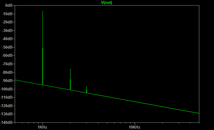
Thanks for the reply - looking forward to your THD measurements. Incidentally, I brought my little super CMOY to work to show a buddy today. He was very impressed how small it was and how great it sounded. I also brought in one of 4 JFET SE class A amps - this one also running off two 9v bat so a fair comparison. He listened to both and AB back and forth using my dT880-250's. He was clearly convinced the class A sounded much better. I asked him why and he says the sound is "smoother" and the mid range has a better tonal balance. I know these opamps are as flat as can be in frequency response so I was surprised by that. Anyhow - I ran a sim of the amp and found it has predominant (but low) H2 and very little H3 and nothing else. So the euphonic H2 is probably what lured him to it. The THD on the super CMOY is probably way better than 0.036%. The OPA1688 has a spec of -108dB THD into 32ohms at 1k and 50mW, clearly lower than what the simple 4 transistor amp was capable of. But sometimes a little H2 secret sauce doesn't hurt. 🙂
http://www.diyaudio.com/forums/solid-state/301164-mosfet-source-follower-headamp-21.html
Anyhow, he really liked that little 4 JFET amp, I ended up giving it to him.
And btw, I am very impressed with how foolproof that protection circuit with SSR works. It is lightning quick - power just cuts, never did I hear a pop or click.
If I want to implement the delay and relay on my other amps, is all that is needed the small sub circuit with the 7812, two zeners, two MOSFETs, a relay and resistor and cap delay circuit? That would be a slick standalone board. Maybe add DC detect and cut-off to it?
Last edited:
I wish I had one of those class A simple amps to hear for myself....I have built most all of AGDR's amps and when I set up blind listening tests for people they have a very hard time picking out the same amp with any certainty. I match the amplitudes and I dont let them see the amp.....use same source song etc....
But like most depending on the mood I am in, time of day and alcohol consumed I often prefer one over another just "because"!! LOL..
Alex
But like most depending on the mood I am in, time of day and alcohol consumed I often prefer one over another just "because"!! LOL..
Alex
I wish I had one of those class A simple amps to hear for myself....I have built most all of AGDR's amps and when I set up blind listening tests for people they have a very hard time picking out the same amp with any certainty. I match the amplitudes and I dont let them see the amp.....use same source song etc....
But like most depending on the mood I am in, time of day and alcohol consumed I often prefer one over another just "because"!! LOL..
Alex
It's a very easy amp to make - costs almost nothing in parts. In my thread I have layout for home etched PCBs. In fact, I made it using a hand drawn Sharpie marker on copper then etched it myself. It's truly one of the best high value class A amps given price and performance.
Schematic is pretty simple:
Ok, so I need to build two of these, one for left and one for right? Will it run off of 9 volt batteries? Volume control?
Alex
Alex
Ok, so I need to build two of these, one for left and one for right? Will it run off of 9 volt batteries? Volume control?
Alex
I don't want to hijack thread so if you have more questions, please go here:
http://www.diyaudio.com/forums/solid-state/301164-mosfet-source-follower-headamp-21.html
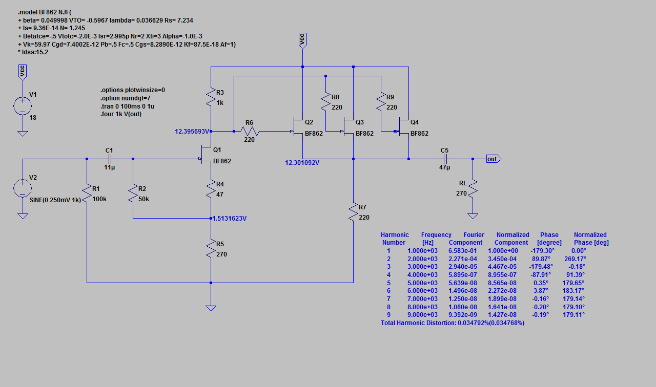
But, yes, two are needed and it runs great off two 9v batteries in series for 18v and I use 50k pot on front end. Silent and buttery smooth volume change - no scratchy noise whatsoever. Works fantastic as portable amp. Even though zero global feedback amp the gain is about 3x - plenty to get loud.
You can see two 9v batteries inside (600mAhr Li-ion should be good for 5 to 6hrs):
Last edited:
If I want to implement the delay and relay on my other amps, is all that is needed the small sub circuit with the 7812, two zeners, two MOSFETs, a relay and resistor and cap delay circuit? That would be a slick standalone board. Maybe add DC detect and cut-off to it?
Yeah it is a handy circuit! The voltage regulator is in there because the amp is battery powered. 12V is less than the minimum battery voltage of 7+7 = 14, so that the relay circuit always has a constant voltage. For timing I came up with something a bit clever and reversed the resistor and diode in the RC delay pair. So instead of sensing the voltage across the timing capacitor, which is the usual thing, it senses the voltage across the resistor. Which in turn requires an inverter, the second transistor. Using the resistor allows you to get the long "tail" on the RC charging curve. A much smaller capacitor can be used, at the expense of that additional transistor and pull-up resistor. And using a zener plus a reverse bias diode across the relay coil for turn-off field collapse results in a faster turn-off than just a single reverse bias diode. That is part of the accelerated turn-off.
As for DC sensing, take a look at AMB's e12 project which does exactly that:
The ε12 muting / protect circuit
Hey nice case you came up with their for your amp!
Last edited:
XRK971 is conducting a "blind virtual audition" of eight DIY headphone amps here:
http://www.diyaudio.com/forums/headphone-systems/303345-blind-virtual-audition-several-headamps.html
The Super CMOY is included in the test, and I think I might be able to pick it out. I hear one specific sound sample (won't say which one, so I don't spoil the fun) which seems to have less distortion and more transparency than all the others. My guess is that it is either the Super CMOY or the Fiio A5, which probably also has low THD. Time will tell. I think X is going to reveal the amp identities in a couple more weeks.
Agdr, you probably have a better grasp of the sound signature of your amp than anybody else. Are you able to pick out the Super CMOY in the comparison?
Last edited:
- Home
- Amplifiers
- Headphone Systems
- OPA1688 Super CMOY, 2x 9V with real ground and headphone relay - PCBs