FO L. Calibration
Thanks Andrej,
The VAS idle bias current is 18 mA, same as FO M ?
.
Everything is exactly the same as per FO M calibration, same procedure to the last detail as described in User and installation manual.
Only trimmer TR3 which sets bias current ie. power supply current of the module, could be rotated CW (clockwise) to set bias current to a higher value: anything in between 280 mA up to 500 mA. Correct bias value (TR3 position) is set when heatsink reaches 45 °C in idle (power on, no input signal).
Thanks Andrej,
The VAS idle bias current is 18 mA, same as FO M ?
.
Last edited:
Thanks Andrej,
The VAS idle bias current is 18 mA, same with FO M ?
.
Yes, exactly the same.
your welcome 🙂
the protection is this one : Modules C1237 Protection pour haut parleur 2 - Audiophonics
using one per chanel to avoid ground loop. and it is powered by an auxiliary output from the smps (20volt or so)
Merci Maxidcx
Bonnes écoutes et bcp de plaisir / enjoy your amp
Claude
I don't want to spoil the joy, but the rise of THD with increasing power is surprising:
at 100W, 0.05% THD is far from the 0.004% announced.
Any explanation?
at 100W, 0.05% THD is far from the 0.004% announced.
Any explanation?
Welcome to the party 
Post #2 shows my measurements with Sound Blaster ZXR card in a controlled lab environment, one channel DUT in separation from SMPS. 😉
Change a supply wire routing and one decade goes away, simple as that. 🙂
Post #2 shows my measurements with Sound Blaster ZXR card in a controlled lab environment, one channel DUT in separation from SMPS. 😉
Change a supply wire routing and one decade goes away, simple as that. 🙂

Faraday cage is a great idea.
A few thoughts.
So far, discussion about choosing M or L is seen as a power issue, apart sound quality improvement from mods to the input section. I cannot find it now but I read somewhere that L was a balanced amp (meaning from input to output) but I could be wrong: that would make a difference in grip to the speaker, if at all possible, given the extraordinary grip that the M module already has. 😎 Please LC, illustrate us.
Also, choosing from different SMPS offers has been seen from the power (reserve) side...the sound quality being unable to be established before use. I know there are other aspects also as reliability (fear of failure), DC sense, etc. My main concern is sound quality, and about this, I read long ago a famous article somewhere about sound quality of electrolytic caps. The authors concluding after a vast comparison of brands that the one aspect that was constant is that diameter was directly related to sound quality, meaning the wider (fatter) the better...maybe that was related to voltage ratings but surely is due to better internal construction. I have arrived to the same conclusion many times.
So choosing multiple small caps of the sufficient voltage rating may be a perfect engineering solution, but if you end with a sub-optimal answer sound-wise, like with Hypex supply, try bigger and fatter caps! When choosing from different SMPS offers, I give my choice to the one that has bigger, fatter cans on the output side. There is nothing wrong (apart price) with using higher voltage rated caps.
(Everybody here knows, I hope, that low frequency sonons need fat caps and fat wires to travel through... 😀 )
I expect your opinions.
M.
Last edited:
Faraday cage is a great idea.
A few thoughts.
So far, discussion about choosing M or L is seen as a power issue, apart sound quality improvement from mods to the input section. I cannot find it now but I read somewhere that L was a balanced amp (meaning from input to output) but I could be wrong: that would make a difference in grip to the speaker, if at all possible, given the extraordinary grip that the M module already has. 😎 Please LC, illustrate us.
Also, choosing from different SMPS offers has been seen from the power (reserve) side...the sound quality being unable to be established before use. I know there are other aspects also as reliability (fear of failure), DC sense, etc. My main concern is sound quality, and about this, I read long ago a famous article somewhere about sound quality of electrolytic caps. The authors concluding after a vast comparison of brands that the one aspect that was constant is that diameter was directly related to sound quality, meaning the wider (fatter) the better...maybe that was related to voltage ratings but surely is due to better internal construction. I have arrived to the same conclusion many times.
So choosing multiple small caps of the sufficient voltage rating may be a perfect engineering solution, but if you end with a sub-optimal answer sound-wise, like with Hypex supply, try bigger and fatter caps! When choosing from different SMPS offers, I give my choice to the one that has bigger, fatter cans on the output side. There is nothing wrong (apart price) with using higher voltage rated caps.
(Everybody here knows, I hope, that low frequency sonons need fat caps and fat wires to travel through... 😀 )
I expect your opinions.
M.
Max,
For me I try to stay away from subjective opinions on sound quality as that is often in the ear of the beholder. If it is possible to check on a specification or measurement to help make a decision then I would tend to go with that.
There are not as many First One Large modules out there and even less feedback on them. I was only trying to point out that a FO L could end up being quite a lot more money, take up more space and deliver way more power than is actually needed. None of that had anything to do with perceived sound quality, only practicality.
The size of the capacitor has an effect on the ripple rating, the higher the ripple rating the less the capacitor will heat up during use and the greater current it can pass. In the same type of capacitor you can sometimes get long and thin and short and fat. I always go for the highest ripple rating that I can get along with the lowest ESR. Many highly praised audio capacitors have terrible specifications the Mundorf Ones LC uses are actually very good for ESR and ripple. You also cannot tell the ripple rating just by looking at it, just check the datasheets of a few and you will see what I mean.
The capacitors I choose have a 3.67A rating and are 16 milliohms each, when two are added together for each rail that is a very high specification cap that is impossible to find in a short fat one at least for a reasonable price.
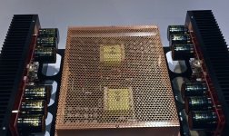
I love this copper shield on the smps. problem is to find/buy it. do you know a european seller for this ?
when it comes to caps and sound, maybe we could differentiate 3 aspects.
- the bass: aibility for the amp and smps to deliver the expected current on time, (and also to absorb the reverse current from speaker emf). here the magic seems to happen with bigger caps and smaller esr (and smaller wire resitance of course) but this is something to explore depending on the response time of the smps.
- the mids-high: here very often on linear psu it is advised to have a MKP in the range 5-20uF, I ve made the test myself some years ago, such a cap on the rail change a lot the sound. Also the inductance of the wires and component leads has some effects.
in fact this can all be summarized by analysing the PSU impedance over the audio band...
this can be simulated to some extend and tested with a network analyser. basically what is the voltage (and phase) variation on the rail depending on the current frequency. this can also be seen as what is the transient repsonse.
The curve you get will have an impact on the sound as an amp as a limited PSU rejection capability. I d say the best is to organize the caps network and wiring for having a very low and flat impedance and flat phase (meaning constant group delay)... easy to say 🙂
The third aspect of this caps is about reducing the ripple on the rails.
with a couple of measurement you can easyly see the impact of the ripple on the output, either as residual or as Inter Modulation component, (or jitter for class-d)
Here the cap which are on the primary side of the smps (400Volt) must not be underestimated. But too much caps here will impact the "PFC" on the mains, and then some trade of is needed.
Also when the amps leaves the Class A, then the signal apears as half sinusoides on each rails (V+/v-) which produce tons of harmonique at the transition point. this in turns impact the rail quality, unless the impedance discussed earlier is flat and very small (in the range of few miliohms) so the amp will be impacted.
so I think LC is right to recommend a combo smps+caps+FO M/L because the results is really linked to the tuning of this chain. All of us playing with other PSU are welcome (and I will continue😛) but our journey to the heaven will not take the same route as for the one following LC recomendation.
in other words, science is behind the sound of our amps, not caps
I d love to see the impedance curve of the hypex (+ various mundorf) on the Drain of the mosfet. this requires a bit of a setup on the bench. I ll try maybe
cheers
Last edited:
I love this copper shield on the smps. problem is to find/buy it. do you know a european seller for this ?
Salut maxidcx, how about this one link (UK seller) ?
Thanks for your opinions, guys. Very interesting and appreciated.
Of course, when I complained about Hypex SMPS I ment mainly the bass/midbass: several opinions, including mine, stated that F.O. M sounded great but the bass seemed wanting...until the added capacitance solved the problem letting little to be desired.
The midrange trick that Maxidcx comments is one that I did not tried yet, because mainly of space...I have tried 1uF in other SMPS and that produced an effect I would say even on "low HF".
About ripple, LC does not recommend active regulation for his amp so I won't try it at all but I plan a CLCRCC linear supply for my next build to compare.
Cheers,
M.
Try them or search similar perforated copper sheets producers. 😉I love this copper shield on the smps. problem is to find/buy it. do you know a european seller for this?

Hi sorry for post here
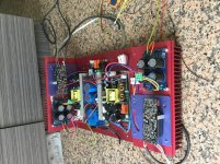
I have to sell 2x SMPS 1200A400 (used ) @ $ 240 + shipping (free PayPal )
Reason for sell
Fund SMPS 3k700 for first one L
Best
Attachments
Guys, sorry for the slightly off topic post (but hey, it's for the better sake of the F.O.)
Today I finally swapped my old balanced power transformer (BPTx; only 1KVA from local technician) for my new 2,5KVA BPTx ordered from a national maker of repute. As you may know the most important feature is that the dual secondaries (0-110/0-110 in my case) must be strict bifilar windings.
(see equitec.com for technical info and expected results)
The Tx plus the iron box must weigt around 50Kg 😱
The improvement is significant to say the least, scarry sometimes. Best USD $300 spent in ages.
You haven't heard your amp yet if you connect it to the wall...
The amp is sounding better and better without direct intervention, only by improving the supplied energy...great work Lazy Cat.
I run the source with another smaller balanced power Tx in series. Now I will use the old 1KVA Tx to isolate the sources. 😎
I hope this helps.
M.
isn't the 156watt maxidcx measured a bit low for 52volt?
maybe the smps doesn't have enough current for more or it could
hit 200watt at 1%?
or maybe both?
maybe the smps doesn't have enough current for more or it could
hit 200watt at 1%?
or maybe both?
Welcome to the party
Post #2 shows my measurements with Sound Blaster ZXR card in a controlled lab environment, one channel DUT in separation from SMPS. 😉
Change a supply wire routing and one decade goes away, simple as that. 🙂
LC,
I am interested in measuring the amps I have as I am using different supplies and different voltages. I have been researching good methods and got some info from maxidcx.
Before I commit to buying any parts for load and voltage divider etc. could you outline what you used to test the First One and how it was connected or a picture if you have one. I want to avoid getting a bad result from an incorrectly setup test.
Thanks
- Home
- Vendor's Bazaar
- First One - mosFET amplifier module