Dear All,
I see that most of us use medium size capacitors for PSU in class A amp (C or CRC configuration).
There are on the market capacitors up to 1F, with size between 0.1 to 0.3 F being quite affordable.
I see the practical advantages of using a single component, but what are the disadvantages ? How come this solution is not that popular ?
Thanks,
Davide
Huge in-rush is one reason. Can be controlled. First cap always takes the hardest hit.
Price and size.
Price and size.
Well, the CRC method acts as a low pass filter and helps considerably to keep the supply clean and costs very little in dollars or efficiency to use.
All FW psu schematic use CL-60 on toroid psu primary.
This is in-rush protection and against thumb on-off noise in your speakers at the same time.
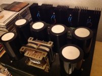
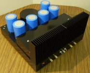
Big caps are bulky and heavy , co$t more. Connected by wire, copper bars , not many pcb's available 😉
Need decoupling with non polarised small caps.
Purpose is filtering noise but i think they work like stored energy reservoir.
This energy is pumped by the music specialy big orchestral , bass & low frequency moments.
They are modest power Class A 20 watts amp´s with luxury BIG WATT´S.
Try by Your Self if is worst the efforts 🙂
This is in-rush protection and against thumb on-off noise in your speakers at the same time.
Big caps are bulky and heavy , co$t more. Connected by wire, copper bars , not many pcb's available 😉
Need decoupling with non polarised small caps.
Purpose is filtering noise but i think they work like stored energy reservoir.
This energy is pumped by the music specialy big orchestral , bass & low frequency moments.
They are modest power Class A 20 watts amp´s with luxury BIG WATT´S.
Try by Your Self if is worst the efforts 🙂
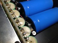
Attachments
A 1F capacitor is useful to use as memory backup, nothing else. They are too big and bulky plus they put a serious strain on the power transformer to keep them charging. A bit like hitting your head against a brick wall would paint a good picture of how the transformer must be feeling.
In an amplifier with an "Audiophile" sticker on the transformer just about sums it up!
In an amplifier with an "Audiophile" sticker on the transformer just about sums it up!
My point actually was: let's say you decide for 100000uF. Is there any difference between using 3 33000uF rather than one 100000uF ?
D
D
A 1F capacitor is useful to use as memory backup, nothing else. They are too big and bulky plus they put a serious strain on the power transformer to keep them charging. A bit like hitting your head against a brick wall would paint a good picture of how the transformer must be feeling.
In an amplifier with an "Audiophile" sticker on the transformer just about sums it up!
@ JonSnell Electronic
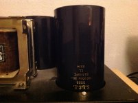
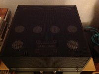
Do you have ready use 20 watts class A with such 1F caps in the psu ?
My are 450 000 uF for mono channel.
He play rock stable and solid sound have his subtle details charm as well.
Think we can use capacitor multiplier circuits or other topology as well.
After my personall experiments ( was 8 watts amp ) i conclude biger capacitance can bring sonic benefits
in some amplifiers , some situations ( audio chain with moderate efficiency drivers )
This is brute force passive psu classic solution between the others.
I am on less theory more practice : solder circuits components , modify and hear what happen in the music.
Btw last days my game was different caps test's in my tube pre-amp.
What your best solutions , response about huge caps use ?
I do like learn something new to build great psu's

My point actually was: let's say you decide for 100000uF. Is there any difference between using 3 33000uF rather than one 100000uF ?
D
As a general rule smaller capacitors have higher ESR and less inductance, see random spec sheet here: http://www.vishay.com/docs/28342/058059pll-si.pdf
But if I am not wrong, if you parallel many small caps, also the ESR goes in parallel so if you put 10 of them, you have to divide by ten.
D
D
But if I am not wrong..
D
That's correct but don't forget the resistance and inductance of the connections between the caps. For an example of a poor implementation, six inches of 24 gauge wire is around 0.013 ohms or over half the ESR of a 10 volt 33,000 uF cap on that sheet.
It's doable, the details count.
I do and have recommend it on this Forum.Would anyone use 24 gauge wire in a power supply?
I wouldn't use anything smaller than 16 awg.
When you use a C input filter using bank of three capacitors, you actualy have an rCrCrC PSU.
The first r is the total of all the resistances in the rectifier/transformer side of the input.
The middle r is the resistance of the traces/wiring used to connect between the first C pin and the second C pin.
The last r is the resistance between the second C pin and the last C pin.
The same happens with the Zero Volt connections.
You cannot avoid having some resistance. "r" can never be zero ohms.
Now think about how those three cascaded filters work.
They give a very low Q 3pole roll-off RC filter.
What does r do?
Would decreasing it slightly help with the filtering?
Would increasing "r" slightly, help with the filtering?
I believe that reducing "r" to closer to zero does not help the performance of the amplifier that follows (it can be a single opamp or a batch or power apamps or a big descrete Power Amplifier).
I believe that there is a small improvement to be had by slightly increasing those interstage "r" to improve the filtering with little loss of output impedance lowering.
I use smaller than the norm for the twisted triplet that feeds the power amplifier.
the "r" and the parasitic inductance react with the supply rail decoupling to create a further stage of filtering that helps remove the HF artefacts that come in along with the DC current. Much of these artefacts are the remnants of the interference on the mains that is never completely removed by the input IEC filter.
Last edited:
in 1980 Walter Jung published an article at the Audio magazine
about the use of capacitor filter banks to an existing amp....
that article must have started it all.....
to bad that i couldn't get his permission to post the article here,
citing safety concerns, he says he had a change of heart....
about the use of capacitor filter banks to an existing amp....
that article must have started it all.....
to bad that i couldn't get his permission to post the article here,
citing safety concerns, he says he had a change of heart....
I do and have recommend it on this Forum.
When you use a C input filter using bank of three capacitors, you actualy have an rCrCrC PSU.
Do you mean that thin wire for non-ground and thick wire for ground, correct?
- Status
- Not open for further replies.
- Home
- Amplifiers
- Pass Labs
- Advantages and Disadvantages of Monster Caps