Hi All.
I'm starting a new 45/2A3 build soon and would like your opinions on a power supply that I have been playing with. I have attached A PSUD2 screenshot for your consideration. It will be optimized for 45, as I have a couple of nice pairs, but I would like to use 2A3 in it as well. I could do this by using a different rectifier when I use 2A3, or I could vary cathode resisters with a switch or both. Any comments or advice would be appreciated.
I'm starting a new 45/2A3 build soon and would like your opinions on a power supply that I have been playing with. I have attached A PSUD2 screenshot for your consideration. It will be optimized for 45, as I have a couple of nice pairs, but I would like to use 2A3 in it as well. I could do this by using a different rectifier when I use 2A3, or I could vary cathode resisters with a switch or both. Any comments or advice would be appreciated.
Attachments
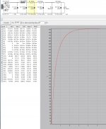
I have two identical old radio chassis that had a 6Y6 final and 5U4 rectifier, so the above power supply is for one of the two monoblocks I am building. The power transformer has 390 volts unloaded and my guess is 365-370 loaded with at least 60ma available. That is a guess however. I have two 2.5 volt center tapped filament transformers on order, and two Electraprint 5k/8 Ohm/3 watt transformers on hand. The transformer voltage seems high for a 6Y6 amp. The person who sold me the two chassis said they had 6Y6 finals, but I got them with no tubes. The original output transformers were tiny.
Last edited:
I am not fixated on any part of this power supply. Please let me know what you would do and why. Straight choke input with no small cap? Less resistance and more capacitance? SS rectifiers?
If I1 is the SE power amp endstage with a 45 or a 2A3, then I think that a big choke and > 1KΩ of resistive impedance seems like a lot. Have you tried looking at what happens when the amp plays a bass note?
The 1200V Cree Silicon Carbide (SiC) rectifiers are excellent, and put an end to worries about SS diodes pulling big reverse-recovery current-pulses. In my 300B-SE, I have used these with big capacitors: 2x 820µF (The 560-1000µF 550V Kemet ALS60 series parts are a good deal from RS UK at the moment).
The ALS60 is a much higher quality part than cheap snap-in types, which degrade much faster, too.
http://www.kemet.com/Lists/ProductCatalog/Attachments/422/KEM_A4042_ALS60_61.pdf
At the amp chassis, I use a FET cap-multiplier and Audio MKPs (30µF 630V LCR FP-AU).
http://www.lcrcapacitors.co.uk/wp-content/uploads/fp-ca-au-630v.pdf
The whole measures much better than the LCLC I used before, and sounds bolder and more powerful, without losing the amp's delicate qualities.
Anyone interested in the 550V caps: The best buy on ALS60 is the 1200µF 550V at RS UK.
Be sure to select production pack (3+ qty). The UK site shows these for GBP 15.36 for 3+ today.
ALS60A122KM550 | KEMET Aluminium Electrolytic Capacitor 1200μF 550 V dc 51mm Screw Terminal Can - Screw Terminals, Radial series ALS60 | KEMET
These screw-terminal caps are hugely better than smaller-case parts. They have a pH-neutral electrolyte that slows the usual degradation mechanism. (If you know anyone with a Fender re-issue guitar amp, you may know how quickly their 22µF 500V types fail).
Please check that your rectifier can handle the IFRM involved at startup. The trafo winding's R and leakage L are usually enough, but it pays to check!
1200V SiC rectifier diodes, from same source:
C4D02120A | Wolfspeed C4D02120A, SiC Schottky Diode, 1200V 10A, 2-Pin TO-220 | Wolfspeed
C4D02120A | Wolfspeed C4D02120A, SiC Schottky Diode, 1200V 10A, 2-Pin TO-220 | Wolfspeed
If I1 is the SE power amp endstage with a 45 or a 2A3, then I think that a big choke and > 1KΩ of resistive impedance seems like a lot. Have you tried looking at what happens when the amp plays a bass note?
Yup. If its going to be single ended then you need to get that DCR down. I would breadboard it with just the choke and see how it sounds. 😉 Your PSU ripple does not need to be vanishingly small.
Note that if you want to be able to "swap" 45 and 2a3, your current draw will be different, and this will affect your B+
Do you want to do fixed (grid) bias or cathode bias? I would advise cathode bias, but then you will need separate cathode resistors for each tube. Also - the primary impedance of your OPT needs to be big enough to accommodate a reasonable load line for the 45.
Lots to consider here. The input/driver circuit as well.
Ian
Thanks for the helpful responses. I have built many SET amps over the past few years, but no DHTs. This will be my first. I have found that with pentode wired as triode SETs, the power supplies with the least amount of resistance in series sound best. Is this a common observation? I have also found that when I can hear hum from an amp, as is the case with my Decware SE84CS clone builds, it is always due to B+ with too much ripple. The SE84CS clone has 280mV on the B+. It sounds great, but it does hum a little. How much ripple is acceptable in the B+ of a DHT amp? In my non DHT amps, I try to get it under 30mV. Is that not required? The other thing is that in PSUD2, the more capacitance that the supply has, the longer it takes to come to full power and stabilize. This is true on start up and when a stepped load is applied. Should I be concerned about this long stabilizing time with a class A SET? I have several pairs of power transformers. In addition to the ones mentioned above, I also have 300-0-300 and 275-0-275 pairs. I also have pairs of 10H 230 Ohm and of 6H 150 Ohm chokes. Thanks again for your past responses. I look forward to your future ones.
I am not sure what the primary impedance is for the Electraprint OPTs. They are the normal copper models with 5k/8 Ohm and rated at 3 Watts. I don't have any particular design in mind, but I am partial to cathode bias. I have used Kemet capacitors as cathode bypass caps before. I try to build completely without electrolytics, but when really large values are required, space and cost restraints make it unavoidable. If values are under 120 or so uF, I generally use film caps, and have a bunch of 40, 70 and 100 uF pairs on hand. It would be relatively easy to install both a tube and a SS rectifier and have them on a switch. Also, I could put in a switch to choose between different cathode resistors values for 45 and 2A3. I haven't chosen a design yet, but I would prefer a simpler one with fewer components, and to use power and OPTs, with choke if prudent, and no other transformers in the design. I'm okay with adding complexity if it means optimizing both tubes via switches or some other means, but simpler is preferred. Any suggestions for an appropriate circuit would be welcomed. I know that I need roughly 330 volts B+, and I would like your help to figure out what would be best. Generally, in the past I have used CRCRC(B+ for power tubes)RCRC(Driver B+) with the supply split into a right and left channel stream after the power tube B+. DHTs are new to me, so I'm hoping to sort out the power supply first. Any suggestions on the best design to choose would be much appreciated. There are many online and, to be honest, the many choices are making it harder to pick one.
In your PSU II simulations, why do your caps have such a high resistance? Surely your caps are low ESR type.
I would use a resistive load since you will most certainly do this in your circuit.
To be honest, I think its best to stick with either 45 or 2a3 and not to try and build both into one amp. However, if you like the work of Thomas Mayer (VinylSavour) then simply source all components from him and build it exactly as he does. Trying to do it on a shoe-string budget is not the way to go.
What are your speakers?
Ian
Last edited:
I left the standard values provided by PSUD2. They are not actually the cap resistance values. I will be using low ESR caps. Probably film caps if the values are under 120 uF or so. The values don't really affect the simulation much do they? I have three pairs of Klipsch speakers, heavily braced Tangent 500 with upgraded crossovers, Heresy II with Crites tweeters and upgraded crossovers, and Quartets, also with Crites tweeters and upgraded crossovers. I also have a pair of Audio Nirvana Classic 10s in a large vented cabinet of their design, which I have had for a while, but still can't wrap my head around. I have a collection of pairs of vintage alnico drivers that I swap into an open baffle as well. The ANs and the alnicos are substantially louder than any of the Klipsch speakers, and must be over 100 DB/watt/m. I understand the argument for building around one tube, but with switches, shouldn't I be able to optimize for two tubes? I'm sure that Thomas Mayer's amp sounds fantastic, but that build is way over the top for me. It's definitely not shoe string. More like shoe store. I would love to hear the two nice pairs of 45s I have, but being able to plug in a readily available 2A3 would be nice too.
PSU II can be used for quite reasonable accuracy when your input parameters are accurate.
Perhaps I should have asked about the speaker sensitivity.
The Klipsch Tangent 500 are noted at having 97 db sensitivity. The Heresy II appear to be about the same if you look at the frequency response curve on the marketing pamphlet. Note the steep fall-off below 50 Hz with the Heresy II which is a typical characteristic of small speakers in small boxes (rogers ls3/5a fanatics take note).
The Audio Nirvana Classic 10 are something like 99 db sensitivity. These might do well in some open baffle or transmission line or whatever... I'm not a speaker guru.
If you don't like to listen to music loud, and don't need sub-sonic pump-you-up super bass then the 45's will be a treat. If you don't have actual 2a3's lying around then don't bother trying to design for them yet.
Make a schematic, then post it for suggestions in the forum.
Ian
Last edited:
Here is my advice: Don't try to build a car with two steering wheels.
Get one design working really well on a breadboard or open frame first.
Ian
Get one design working really well on a breadboard or open frame first.
Ian
Sounds like a plan. I need to put together a compact and portable system for breadboarding circuits. I don't really have the room to set up a breadboarded circuit and leave it there while I work on it over time. Also, I would need to bring the breadboard to the place where I would attach it to source and speakers. Breadboarding requires a dedicated space and I don't really have one. That is why I tend to sim, use proven circuits, and ask for advice from folks who are knowledgeable and have already done it. I would need something that is set up on a board and can be moved around easily. I will work on it.
Last edited:
Here is another PSUD2 sim that looks better. I changed both of the capacitor values in order to reflect those of the actual caps that will be used. What are your opinions on the bypassing of large electrolytics with film caps in power supplies? I prefer to use all film in my builds, but I may use an electrolytic for one of the two larger caps in the supply.
Attachments
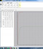
I was thinking about using a 100uF electrolytic and a 15uF film cap together. Is there any point to using the film?
Hello,
I would like to understand one thing about S.E amplifier power supplies:
An SE amplifier produces large current variations. However, the vast majority of amplifier power supply diagrams that I see on the web are minimalist: recovery and filtering, that's it. In fact, I saw only one or two whose voltage was regulated.
Why ?
Is it to compensate for the harmonic distortion of the tubes?
Regards
I was thinking about using a 100uF electrolytic and a 15uF film cap together. Is there any point to using the film?
Input capacitor, I would just use a good DC-link capacitor.
Then you can use good electrolytics like the ALS type. I have some made by BHC, 330uF/500V (550V surge), and they are very good.
I would also consider a good capacitor multiplier after the first CLC.
The film capacitor has better filtering capability, the electrolytic is a better tank, generally speaking, although you can now find DC-link capacitors in large values if voltage requirement is not exaggerated (less than 500-600V) and their losses are still better than equivalent electrolytics.
The filtering I refer to is especially all the garbage coming through the rectifiers (which also includes products from the main) that is not related to 50-60Hz pulse.
Paralleling caps, I did not find it works so well. You either chose to go in one way or another.
The filtering I refer to is especially all the garbage coming through the rectifiers (which also includes products from the main) that is not related to 50-60Hz pulse.
Paralleling caps, I did not find it works so well. You either chose to go in one way or another.
What I am not understanding here is that you are simulating a power supply for constant current consumption when this current consumption is not constant. Why please?
- Home
- Amplifiers
- Tubes / Valves
- New 45/2A3 amp power supply question