All I know is the returns because of sound have plummeted to near nothing. And THAT'S what matters. 🙂
Interesting, do you think anyone has significant returns based on sound? The use of the verb plummeting has some not so nice implications.
Robert - Please PM me, Paypal used my old address for my order. It would be nice if you socketed the 8-legs.
Last edited:
There are probably some markets where it's like selling apparel by mail order. Picky shopper, and you can't try the product in a store near you? No Problem!
Ok got it, LCRMKIII with sockets and change of address. I used to get about a return a month. Now I'm on a 4 or 5 month streak with no returns due to sound. 😀Interesting, do you think anyone has significant returns based on sound? The use of the verb plummeting has some not so nice implications.
Robert - Please PM me, Paypal used my old address for my order. It would be nice if you socketed the 8-legs.
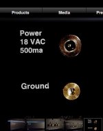
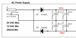
Scott, I see that the LCR MkIII uses an AC-to-AC wall wart (image 1 below) plus half-wave rectifiers (stated in post #81814 ). So does the O2 headphone amplifier (image 2 below) which I own and am experimenting with.
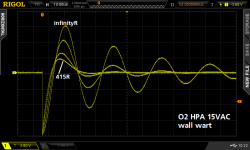
I'm finding that the low-cost construction of the transformer inside the wall wart, plus the long cable directly attached to the secondary, work together to produce unusually high leakage inductance. This gives rise to unusually large amplitude oscillatory ringing when the diode turns off. Image 3 below shows the O2's wall wart without countermeasures (labeled "infinityR") and with countermeasures (labeled "415R").
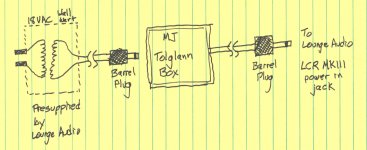
After grinding through the math in the appendix of the Linear Audio diode+snubber article, I believe it is possible to construct an optimal countermeasure for the LCR MkIII's transformer, simply based upon equations, measurements of similar wall warts, and intelligent guardbands. And I have done so. I've got a little box that I call "Tolglann" which plugs in series between the wall wart and the Lounge Audio preamp. Just a little in-line blob. It tames the oscillatory ringing of the secondary circuit.
Based upon my experimental results with Tolglann and the O2 headphone amplifier, I think there's a very good chance you will like the way your LCR MkIII sounds with Tolglann installed, better than with it not installed. You could have a family member arrange a very quick and easy blind test for you, using a paper bag to hide the presence or absence of the Tolglann. It doesn't have to be a "sighted" test.
Let me know if you are interested and I will ship you the Tolglann right away. The parts inside are extremely inexpensive; you can keep the Tolglann after the test, no need to send it back to me.
I'm finding that the low-cost construction of the transformer inside the wall wart, plus the long cable directly attached to the secondary, work together to produce unusually high leakage inductance. This gives rise to unusually large amplitude oscillatory ringing when the diode turns off. Image 3 below shows the O2's wall wart without countermeasures (labeled "infinityR") and with countermeasures (labeled "415R").
After grinding through the math in the appendix of the Linear Audio diode+snubber article, I believe it is possible to construct an optimal countermeasure for the LCR MkIII's transformer, simply based upon equations, measurements of similar wall warts, and intelligent guardbands. And I have done so. I've got a little box that I call "Tolglann" which plugs in series between the wall wart and the Lounge Audio preamp. Just a little in-line blob. It tames the oscillatory ringing of the secondary circuit.
Based upon my experimental results with Tolglann and the O2 headphone amplifier, I think there's a very good chance you will like the way your LCR MkIII sounds with Tolglann installed, better than with it not installed. You could have a family member arrange a very quick and easy blind test for you, using a paper bag to hide the presence or absence of the Tolglann. It doesn't have to be a "sighted" test.
Let me know if you are interested and I will ship you the Tolglann right away. The parts inside are extremely inexpensive; you can keep the Tolglann after the test, no need to send it back to me.
Attachments
If this helps any,
I use a Hexfred as a 1/2 wave rectifier in series with a 2.2 ohm resistor. That dumps into a 1000uf 35v Panasonic FM series cap in parallel with a 0.1uf Panasonic PP cap.
In parallel with wall wart secondary is a shubber consisting of a 0.47 uf pp cap series with a 100 ohm resistor.
There are two ferrite beads in line with the hot side of the wall wart.
I used to use a 1n5819 1/2 wave rectifier. The Hexfred was a game changer! I had to go on a long path of re-voicing the circuit because it was soo very much cleaner.
http://www.mouser.com/ds/2/196/hfa08tb60pbf-935464.pdf
Last edited:
Let me know if you are interested and I will ship you the Tolglann right away. The parts inside are extremely inexpensive; you can keep the Tolglann after the test, no need to send it back to me.
Thanks I'll keep that in mind, for now I'll try everything "as is".
Thanks Morinix and Mark for your inputs on this voltage doubler power supply, and its potential problems.
I used this very supply for the first Vendetta Research product back over 30 years ago, in a 'transient perfect' crossover. For economy, I used a 24Vac wall-wart and the very same voltage doubler, using the same diodes as well. NOW, I see the problem! I should have used high speed-soft recovery diodes to reduce the problem of the diodes recovery problems, as well as other 'fixes' as well. I would bet that is one of the reasons I only got modest listening response by the audio reviewers at the time. I knew that the rest of the circuit was simple, and used the highest quality performance parts, so what did I do wrong?
Well, I used a surplus Wall-wart and standard 1N4003 or so diodes. Now, it makes sense.
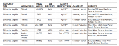
John, you could have / still can observe the disease, and its cure, on a 1960s vintage oscilloscope. Just use two channels, AC couple them both, and display (A minus B). The 1N400x diodes and the crappy trafo produce such a huge ring-a-ding-ding that gain imbalances and offsets between the two scope channels are swamped out by the giant differential mode signal. Even better, use one of the purpose built differential amplifier plug-in modules shown below. Jim Hagermann recommends the 7A22. I'm sure you had / still have a Tek mainframe scope! When tuning the countermeasures you want the ability to view teeny signals and watch them shrink to zero as you twirl the dial(s).
If you find yourself away from your own lab and lacking a differential plug in module, you could of course simply choose to do the job in two steps: (1) measure R, L, C using low cost scope set to (A minus B) with no countermeasures and terrible diodes; (2) compute optimum component values using calculus, drop them in, and replace terrible diodes with good ones.
_
Attachments
I've been looking for differential amplifiers like that, but unsuccessful for two main reasons:
- limited common mode range;
- excessive monetary range 😎
Jan
- limited common mode range;
- excessive monetary range 😎
Jan
Used to have Tek scope dual isolator probe. Quite a bit of common mode range. Like these: TEKTRONIX A6902B ISOLATOR | eBay
Used to have Tek scope dual isolator probe. Quite a bit of common mode range. Like these: TEKTRONIX A6902B ISOLATOR | eBay
That's a nice one!
Jan
A current probe should show the same thing, won't it?
In prrincple yes, but the problem with current probes is that they have relative high noise. A good used DC to several MHz probe with probe amp will set you back several kilo-bucks and will still have almost 1mA noise level.
Jan
A good used DC to several MHz probe with probe amp will set you back several kilo-bucks and will still have almost 1mA noise level.
These are good low noise probes.
N2821A 3 MHz/50uA High Sensitivity AC/DC Current Probe (1-ch) | Keysight (formerly Agilent?s Electronic Measurement)
Last edited:
These are good low noise probes.
N2821A 3 MHz/50uA High Sensitivity AC/DC Current Probe (1-ch) | Keysight (formerly Agilent?s Electronic Measurement)
Well you can debate whether this is actually a current probe in the usual sense. It is really a sensitive voltmeter paired with a current sense resistor that needs to be in the circuit to be measured.
So it is not galvanic isolated from the circuit to be measured as with a 'real' current probe.
Jan
Yes but you need to buy a whole boatanker scope to be able to use it!
Jan
Yes but you need to buy a whole boatanker scope to be able to use it!
Jan
How about a DIY 7A22?
Amen Brother!How about a DIY 7A22?
The 7A22 schematic + service manual are online; I counted only twenty nine transistors (considering a dual device to count as two transistors). How difficult could it be to slap together a quick clone??
- Status
- Not open for further replies.
- Home
- Member Areas
- The Lounge
- John Curl's Blowtorch preamplifier part II