Q501/502 are regulator transistors - JFETs Q301/2 act as muting switches
As suggested, I'm not going to concern myself with the above for the time being.
I agree about "shotgunning" as it is totally a method to circumvent understanding the circuitry and I am, sad to say, guilty of that. It did once result in a successful conclusion but I have since learned I got lucky.
I have yet to power up the receiver but did take your advice to check the removed TO92 transistors. Not the last batch I removed, but those previous. I kept those ones and labeled them with their position.
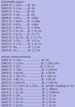
What I found is is that Q405/406/401 were damaged. If it would help, I could elaborate with actual readings.
So at this point, I have what I think is the valid concern that should I turn on power, these transistors will be damaged again.
Since all electrolytic capacitors are new as are the "fusable" resistors and Zener diodes, I am unsure of what to do next.
As suggested, I'm not going to concern myself with the above for the time being.
I agree about "shotgunning" as it is totally a method to circumvent understanding the circuitry and I am, sad to say, guilty of that. It did once result in a successful conclusion but I have since learned I got lucky.
I have yet to power up the receiver but did take your advice to check the removed TO92 transistors. Not the last batch I removed, but those previous. I kept those ones and labeled them with their position.
What I found is is that Q405/406/401 were damaged. If it would help, I could elaborate with actual readings.
So at this point, I have what I think is the valid concern that should I turn on power, these transistors will be damaged again.
Since all electrolytic capacitors are new as are the "fusable" resistors and Zener diodes, I am unsure of what to do next.
Have you been using a Mains Bulb Tester to power ON this amplifier?
Yes. Upped it from 40W to 60W some time ago.
With power on, there is still no bias current present at R471 and adjusting the pot has no effect. I am not sure what you meant by output node but thought it may be output to the speakers so measured for DC offset which is (-)2.5 volts on left channel and (+)11.4mv on right.
I measured at BK1 and got (-)2.5 volts on both lugs. For the hell of it, BK2 has (-)11mv. These I guess are speaker protection.
BK1 is connected to the emitters of Q427 and Q429 - both just replaced.
According to the schematic, it looks like there should be +/- 43V at their collectors yet I'm measuring +/-60V - and that is with a 60W bulb in the DBT.
Hi
The output node should be electrically similar to the +output terminal, as you thought but I meant to distinguish between measuring voltage at the output terminals and in the amplifier itself, at the junction of Q427,429 emitters. This is often referred to as the amplifier's output node and it's before any messy relays, coils and switches that may be bad. You could measure at the breaker's input terminal too but I didn't know whether that would be easy to identify or not. You can always identify and access the emitter of a TO3P power transistor though, from either top or bottom. Anyway, there doesn't seem to be a problem there.
On to the high voltage problem which seems new:
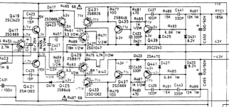
Back at #100, you tabled voltages measured in the L channel output stage and you can see a 1-2.5V offset there, going right back to Q417/419. The transistors involved (Q431,435,439 in + rail and Q433,437,441 in the - rail) form high power switches so that when a particular voltage threshold is reached, they switch in the boost voltage supply to the output transistor collectors, or as much of the 71V is available due to the DBT. This should not occur until a certain output voltage threshold is reached though. So no 70V (or less due to DBT) at the collectors of 2SD1047/B817 until the output level demands it. With no or low output, you should measure only 43V at the collectors (or less, due to DBT).
The switching threshold for each rail is sensed and set by zeners D431,433 in the base circuits of the actual signal-level switching transistors Q439,441. These have to be good to switch the rails correctly so if a rail voltage at the output transistor collectors is constantly high, you know where to start looking or at least start thinking about what's wrong. I imagine that the threshold is higher than the offset of a few volts - perhaps around 35V so I don't think the small offset is the main problem. Perhaps its a result of it. I'm still puzzling over this but here are some relevant details for convenience.
The output node should be electrically similar to the +output terminal, as you thought but I meant to distinguish between measuring voltage at the output terminals and in the amplifier itself, at the junction of Q427,429 emitters. This is often referred to as the amplifier's output node and it's before any messy relays, coils and switches that may be bad. You could measure at the breaker's input terminal too but I didn't know whether that would be easy to identify or not. You can always identify and access the emitter of a TO3P power transistor though, from either top or bottom. Anyway, there doesn't seem to be a problem there.
On to the high voltage problem which seems new:
Back at #100, you tabled voltages measured in the L channel output stage and you can see a 1-2.5V offset there, going right back to Q417/419. The transistors involved (Q431,435,439 in + rail and Q433,437,441 in the - rail) form high power switches so that when a particular voltage threshold is reached, they switch in the boost voltage supply to the output transistor collectors, or as much of the 71V is available due to the DBT. This should not occur until a certain output voltage threshold is reached though. So no 70V (or less due to DBT) at the collectors of 2SD1047/B817 until the output level demands it. With no or low output, you should measure only 43V at the collectors (or less, due to DBT).
The switching threshold for each rail is sensed and set by zeners D431,433 in the base circuits of the actual signal-level switching transistors Q439,441. These have to be good to switch the rails correctly so if a rail voltage at the output transistor collectors is constantly high, you know where to start looking or at least start thinking about what's wrong. I imagine that the threshold is higher than the offset of a few volts - perhaps around 35V so I don't think the small offset is the main problem. Perhaps its a result of it. I'm still puzzling over this but here are some relevant details for convenience.
Attachments
Last edited:
Regarding the higher than normal voltage present at D1047/B817 collectors. If I understood correctly D431/433 would control this? Both diodes seem to be OK with about 8 volts across them and using diode check mode with one leg lifted, OL one way and about .65 the other. But I believe you pointed out earlier that the latter was irrelevant with Zener diodes.
I pulled transistors Q439/441 which tested fine. Voltages on them is 43V at E & B and about 70V at C which seems to correspond to the schematic.
I pulled transistors Q439/441 which tested fine. Voltages on them is 43V at E & B and about 70V at C which seems to correspond to the schematic.
I may have found something. Trying to understand where 70 volts was coming from, I think it could be from Q435. Originally that was a 2SB649 with an E-C-B pinout. What I replaced it with was one of those Darlingtons - 2SB681 with a B-C-E pinout.
I have not gotten farther than that. When time allows I will check original pinouts for Q431/437/433 plus the corresponding ones in the other channel.
Back around post #58, you mentioned a switch made by the factory to Darlington transistors. It looks like those replacements I installed have mirror image pinouts of the originals. If so, I will turn them around and hope they are not damaged. I only have two of each left - not enough to do both channels.
That would be so if they were a different package but darlington type or not, the pinout for all TO126 package parts should be the same. Yes, they are reverse order pinouts to larger plastic power transistor packages such as TO220, TO3P regardless of Brand or type. If your meter can supply enough test voltage, you could test the Vbe as being 2 diode voltage drops or ~1.3V for a reasonable indication of health and pinout and then test C-E shorts while you are at it....It looks like those replacements I installed have mirror image pinouts of the originals.....
Last edited:
Well that eureka moment was short lived and you were very correct. By mistake, I was looking at the data sheet for a different transistor and just the diagram, not the package illustration.
I pulled Q435 to test and it is fine. But I also pulled Q431 (BD912) and 433 (BD911) and they are not. There is a voltage drop where the reading should be OL. I have 2 of each leftover so can replace those on this channel along with those in the other if need be.
It seemed logical to extract all 4 transistors Q437/433 and Q435/431 and check voltages at their pads. All correspond to those indicated on the schematic, allowing for the 60W DBT.
Unless you think otherwise, I shall re-use the Darlingtons at Q437/435 but install new BD912/911's at Q431/433. Once done that, I will check for reduced voltages at the output transistor collectors.
With the those four TO126 transistors removed, collector voltage at output transistors Q427 & Q429 is now down to 36 volts with the 60W DBT. Hopefully replacing the two damaged Darlington's will not change that. It would be satisfying to know what could have hurt them.
The voltage present at the collectors of Q430 & Q428 output transistors in the other channel is also high at 67 volts. I have not yet removed the TO126's to check but I expect the two Darlington's there are damaged as well.
It would also be satisfying to understand what happened to do the same damage on both sides.
It's encouraging to see some things becoming clearer and to at least see a few a voltages restored. That's progress, I think.
Yes, It takes a lot of current to blow BD911/912 and that would only occur when the output transistors were also blown. I could only speculate on how the damage began but consider that there is only quite slow operating output protection, so the power amplifier is prone to damage from shorted speakers/leads. It's not hard to imagine what some owners will do (and the end result) when faced with even a simple task like fitting speaker leads. In my experience, it's seems to be a case of keep trying anything until something happens. When that fails, try the same with the other channel too!
I once had an expensive Luxman amp given to me for repair, speaker leads still attached. The leads were not only in several spliced short lengths but instead of being insulated from each other at each splice, they were twisted together in a corroded mess of wire strands that had been that way for some time and would have been shorted almost continually as often as it was used. Even with protection circuits, not much could survive that degree of blind stupidity. Luckily, it was only the output stage transistors that failed but it could easily have been even worse.
Last edited:
Output transistors can fail if the amp is driven to gross over heating.
They can also fail if the over driven speakers go short or even reduce their impedance a bit.
The catch 22 is repairing the amp and then trying to drive the blown speakers.
One blows the other and vice versa.
I kept a close eye on speaker leads when I was running a mobile disco.
The leads are constantly plugged and unplugged.
They can get tripped over and damaged and the wires get stretched or pulled out.
So with those transistors out (Q431/432/433/434/435/436/437/438) I thought I'd review my handy work only to discover a gross error. I compared polarity of the transistors listed in the service manual with those of what I put on the board and low and behold, I got the Darlingtons mixed up - put a PNP where an NPN should go and visa versa. No wonder they got damaged.
Now armed with this wee bit of information, I am not going to re-use any of those 8 transistors. I ordered duplicates so have just enough to do it again.
Now armed with this wee bit of information, I am not going to re-use any of those 8 transistors. I ordered duplicates so have just enough to do it again.
One more protection, actually two.
a.) add a pair of small power diodes from output rail (speaker out) to the supply rails on the PCB. Might be easier to add these on the back of the PCB.
b.) add a pair of small power diodes from power ground to supply rails. Again maybe more space on the back.
I use 1n4004 and they seem to be robust enough for 100W to 170W into 8ohms amplifiers driving some big reactive speakers.
When you use the Mains Bulb Tester to power your project next time and you have accidentally wired that 3 wire cable incorrectly the bulb will turn on and the diode will limit the reversed voltage from rail to power ground to <1V and save you blowing up the amplifier and also save your electrolytics from reversed voltage. Oh and it saves blowing the mains fuse yet again.
Putting new Darlington's in their correct locations improved things somewhat but not completely. Voltage at the collectors of those output transistors has gone down to (37v with 60w DBT) on three out of four. Q427 is lower but went down to 45v.
Reviewing the schematic prompted me to check diodes D421/423 and things are not as they should be. D423 looks to be normal at both ends (38v) but D421 does not. That one has 62v on the bar end but 38v at the other.
Since a diode cannot increase voltage, I looked elsewhere. The schematic shows that diode's bar end connected to the 71v source at Q435 base and Q439 emitter but through C433, identified as 440pf. It is a green disc which I just Google searched and see it is a ceramic.
I did not think a capacitor affected voltage but at this point it seems to me the only device that that the higher voltage can emanate from.
I also checked for the presence of bias current across R471 and R472 which had formerly been zero. Now, there is 48v at R471 but still zero at R472. Adjusting bias pots still has no effect in either.
Today I will get some of the appropriate 430pf disc capacitors if possible to see if a new one changes things.
I am still puzzled why the bias pots are not having any effect.
Reviewing the schematic prompted me to check diodes D421/423 and things are not as they should be. D423 looks to be normal at both ends (38v) but D421 does not. That one has 62v on the bar end but 38v at the other.
Apologies for jumping in and I'm not really sure where you are up to. I just keep seeing the thread week after week 😀
The most probable reason you have 62 volts on the cathode of D421 is because Q431 will be 'on'.
A fault in that area, or the lower negative rail switch should not affect the basic operation of the amplifier. In other words, fault or not in that area, the amp should play music and adjust correctly. I don't know if it does or not 🙂
Assuming Q431 and Q433 are OK then you can simply remove their drivers Q435 and Q437 and concentrate on fixing the main amplifier (if needed).
No apology needed and thanks for the suggestions. But if you say it should play, as in with CD player connected and through speakers or headphones in it's present state, it does not. There is no sound of any kind.
I did discover though that I'd neglected to solder the legs of Q433 yesterday but did so just now. The result is that there is now 62v at the cathode of D423. So I guess Q433 must also be "on".
For the sake of knowing, I measured the E-C-B voltage present at Q433/437 and Q431/435 and there is +/-62v at all of them. To compare, Q428/434 and Q436/432 have +/-62v at E & B but 36v at C.
Since I do not seem to be able to understand or correct whatever is ailing this receiver, despite all the excellent assistance I've been given, I believe it is time to pack it in. It has been, as you've observed, been going on a long time.
Last edited:
Yes, it should all play through speakers no matter what fault is present in that area of the circuit. All that area of the circuit does is allow a higher rail voltage to be available for transients.
Its up to you if you would like to carry on. I'd probably say a deciding factor in that would be how good the print is holding up. If you think its worth it 🙂
Its up to you if you would like to carry on. I'd probably say a deciding factor in that would be how good the print is holding up. If you think its worth it 🙂
The print is not in unending supply and that's for sure. I started this thread on October 3 last year and despite all the dozens of hours I've spent and parts I've purchased there's been no sign of successful conclusion so I'm going to cut my losses. In hindsight, I should have left this receiver in the trunk of the car I towed to the steel recycler.
In the time since, I found two other audio components likewise abandoned and ironically both were NAD. One was another receiver which only needed fuses and lamps. The other was a CD player with broken plastic disc tray parts. All the pieces were still inside the player and only needed gluing back into place.
In any case, I am going to let this 7240PE continue the journey I interrupted. I have gotten pieces of NAD gear up and running before and will probably try doing so again if the opportunity arises - except those with the letters PE in the model. Besides, a Sony EL-7 Elcaset with a dysfunctional transport has been sitting here since last fall that I'm going to have a crack at. So I can use the dining table space the 7240PE has been occupying the past 5 months.
- Status
- Not open for further replies.
- Home
- Amplifiers
- Solid State
- NAD 7240pe - all output transistors failed?