Hi guys.
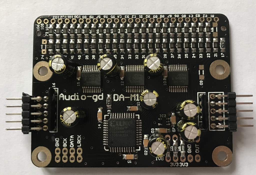
I just came across the Audio-GD DA-M1 R2R module board through the Head-fo forum.
I have very little understand or DIY experiecne with digital sources, so im not yet sure how to assemble a fool functional DAC from it, but if o got it right, you just need to add a USB to I2S \ SPDIF board (if you need USB), a good power supply and an output stage (maybe you can use an interstage transformer here?) of your "choice".
Seems like a very Cheap and easy way to assemble an R2R dac.. What do you guys think?
Tank out.
I just came across the Audio-GD DA-M1 R2R module board through the Head-fo forum.
An externally hosted image should be here but it was not working when we last tested it.
I have very little understand or DIY experiecne with digital sources, so im not yet sure how to assemble a fool functional DAC from it, but if o got it right, you just need to add a USB to I2S \ SPDIF board (if you need USB), a good power supply and an output stage (maybe you can use an interstage transformer here?) of your "choice".
Seems like a very Cheap and easy way to assemble an R2R dac.. What do you guys think?
Tank out.
Last edited:
If you're after multibit sound there are cheaper and simpler ways to go - for example using the TDA1387 DAC chip. But I agree for those who wish to experiment with discrete DACs this looks like the cheapest choice going. I know nige2000 has ordered some - Tír Na HiFi • View topic - Another interesting r2r dac
Actually, im not even sure what im after 
I Dont have any need for Hi-res capabilites, and thats why i use the EAD DSP7000. As old as it is, coupled with the JLsound I2SoverUSB board i have, it sound quite incredible.
But im always looking for a new project (as if i dont have about 4 pending right now..), and building an R2R dac looks very interesting. obviously, there's always the Soekris board to consider as well (and i am considering it).
What i would really love is to experiment with an interstage transformer as an output stage for a dac, but im not sure either the Soekris Board, or the Audio-GD board can do that...
Tank out.
As you don't need hi-res you could get into 'R2R sound' more quickly by acquiring one of these DACs - https://item.taobao.com/item.htm?spm=a230r.1.14.36.hc4FES&id=42124644877&ns=1&abbucket=18#detail then modding it like crazy 😀
Alternatively post up the details of the transformer you have in mind and let's take a look at whether it might be suitable?
Alternatively post up the details of the transformer you have in mind and let's take a look at whether it might be suitable?
It's not really a DAC, just a single shift register with a not very precise R-2R network.... You still need multiple boards, power supply, spdif receiver, low jitter clock, fifo buffer, digital filter, dsd decoder, volume control, output buffer and something to control it....
It's actually cheaper to use a dam1021-05 that have all you need.... I might be a little biased, but I'll say go for the soekris board 🙂
It's actually cheaper to use a dam1021-05 that have all you need.... I might be a little biased, but I'll say go for the soekris board 🙂
Last edited:
I'd say it does indeed look like you're biassed - for what reason would a digital filter be needed?
I'd say it does indeed look like you're biassed - for what reason would a digital filter be needed?
Antialiasing filtering ? I know some like NOS, but there is a reason why all Audio DAC chips have the antialiasing filters built in (or come with a external filter chip)....
On a point of order, you probably mean 'anti-imaging filtering'. The filter can be built analog as well as digital, admittedly the analog one won't be as stable over time and component tolerances. It probably leads to better dynamics though.
The filter can be built analog as well as digital...
Tell me, how do you make a digital anti-imaging filter? The images are created by the digital-to-analog conversion process. By definition, a digital filter will precede the conversion and cannot have any effect on the images created.
You're asking the wrong person - its soekris who introduced the digital anti-imaging filter, not I.
Tell me, how do you make a digital anti-imaging filter? The images are created by the digital-to-analog conversion process. By definition, a digital filter will precede the conversion and cannot have any effect on the images created.
Yeah, I used the wrong term, an ADC have anti-aliasing filter, a DAC have anti-imaging filter, also called reconstruction filter....
You can do the filter two ways:
1) Oversampling and digital filtering, usually a FIR filter, then a soft analog filter to remove the then higher frequency image.
2) A very sharp analog filter, nobody do that nowadays as it's hard to make and expensive.
And then there are people how prefer non over sampling.... We should not go into a discussion about that, lets just say there are advantages and disadvantages to it....
Last edited:
You're asking the wrong person - its soekris who introduced the digital anti-imaging filter, not I.
No, soekris claimed every DAC chip had a built-in anti-alias filter. You corrected his terminology and further claimed a anti-imaging filter could be either analog or digital.
You corrected his terminology and further claimed a anti-imaging filter could be either analog or digital.
You'd do well to read what I wrote rather than just respond to what you thought I wrote. Here's what I said -
The filter can be built analog as well as digital, admittedly the analog one won't be as stable over time and component tolerances. It probably leads to better dynamics though.
Here 'the filter' is referring to the complete filter that the DAC needs which is typically a combination of digital and analog. So when I said 'analog as well as digital' it was shorthand for saying 'pure analog as well as the more normal hybrid of analog and digital' as I figured soekris already knew how to design a DAC.
Incidentally how's your DAC design coming along, I've not read any updates for many months now? Is it ready to hit the market?
Last edited:
You can do the filter two ways:
WRONG, again. The only way to remove images is with an analog filter. Images do not exist in the digital domain.
The NOS lovers either don't mind the sound of images or they rely on the inherent band-limiting of their audio systems to filter them out.
The NOS lovers either don't mind the sound of images or they rely on the inherent band-limiting of their audio systems to filter them out.
As a NOS lover this doesn't apply to me. So looks like WRONG again 😀
Ok, i plan to move forward with this board.
The plan is to get two board for a single ended dac (i don't have any need for balanced output), and start with the minimum amount of parts needed for a working unit (just like the diagram for a NOS dac seen on their website). I will use the JLsound I2SoverUSB board as the input board.
I would like to use an external power supply board as well, and wonder if i should really remove the existing power supply from the DA-M1 board (like the manufacturer recommends) or just add something like a SALAS shunt regulator on top of it (DC to DC). what do you guys think?
For the output stage, i plan to use tubes. i have a pcb a friend made me that uses two ecc82 tubes and UTC a-20 output transformers, i might use that, unless there is a more recommended approach (i'm open for jfets as well).
Thank you all.
Tank out.
Ok, i plan to move forward with this board.
The plan is to get two board for a single ended dac (i don't have any need for balanced output), and start with the minimum amount of parts needed for a working unit (just like the diagram for a NOS dac seen on their website). I will use the JLsound I2SoverUSB board as the input board.
I would like to use an external power supply board as well, and wonder if i should really remove the existing power supply from the DA-M1 board (like the manufacturer recommends) or just add something like a SALAS shunt regulator on top of it (DC to DC). what do you guys think?
For the output stage, i plan to use tubes. i have a pcb a friend made me that uses two ecc82 tubes and UTC a-20 output transformers, i might use that, unless there is a more recommended approach (i'm open for jfets as well).
Thank you all.
Tank out.
I'd say keep things simple at first and pull power from the most convenient source. This board is brand new so I wouldn't invest too much until we know it's up to snuff.
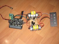
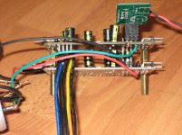
I had two boards set up following "The most simply USB NOS DAC circuit diagram" way as shown on the Audio-gd website. I deviated slightly by substituting 1.3k resistance in place of the 2.2k resistance in the low pass filter (I had higher quality resistors that added up to 1.3k). I also tried various capacitance in both the low pass and high pass filter positions.
I fed the setup with I2S from WaveIO to Iancanada FIFO, isolator, and Dual clock boards. Power was from a diy regulated 5v supply to an Iancanada TPS7A 3.3v regulator. Data was from a HP Chromebox running Debian and MPD with oversampling using SOX.
As can be seen from the photos, I tried to keep everything neat and the I2S lines were less than 100mm long.
My first listening impression was that it sounded good - maybe a bit more forward than my diy TDA1541A dac built on a copper foil covered veroboard that is fed by Iancanada's FIFO and I2S to PCM boards. But after a while I noticed something that started bothering me. On quieter passages I heard a low hiss-like sound that seemed to change with the music (distortion?). It was also really noticeable at the at the end of songs when the music faded in volume.
I then tried changing the low pass capacitor value but that did not seem to have much effect. In conjunction with the 1.3k resistor, I tried 1200pF, 2000pF, and 3000pF, which correspond to 102kHz, 61kHz, and 41kHz respectively.
I also tried different NOS vs oversampling. I tried 44.1/16, 96/24, SOX oversampled 4X and 8X. The low level noise was still there.
I did some reading on the internet and it seemed that nige2000 at the Tir Na HiFi forum also noticed something similar to what I heard:
Another interesting r2r dac - Page 7 - Tír Na HiFi
After an overnight burn-in, I listened some more today but in the end I couldn't stand listening to this setup because of the low level noise, so my TDA1541A is back in play. What a sonic relief.
I don't know what the issue was. It would seem to me to be something digital and not analogue. In other words I don't think it has to do with the simple output filters. Maybe it is something with the zero crossing glitch or who knows what.
Perhaps a dual board "push-pull" setup per channel would give a better outcome? I will wait for others to try and see whether they get different and better results than I did.
And another thing - the output level with the "simple" output circuit has enough voltage that another gain stage is not required in my system. I had initially connected it to the 5842 (mu of 43) tube stage that follows my TDA1541A IV resistor and the volume was way too high. So if a tube output is desired, a buffer would probably be more appropriate.
Attachments
Thanks for your report.
I have received my boards but have not done anything with them yet.
The audio-gd website is confusing. I thought I understood that it was not recommended to have two channels that close to each other. You are supposed to do the stacking for the push-pull connection (and balanced) but it looked like he was saying not to do with this for a simple stereo connection.
Whether that would make any difference is unknown to me!
From the webpage:
Recommend one channel balance assemble guide (we are not recommend assemble two channels as below):
Which is written above the pictures of the push-pull stack.
Worth another try?
Last edited:
- Status
- Not open for further replies.
- Home
- Source & Line
- Digital Line Level
- Audio GD DA-M1 R2R Dac Module