Although after many years of listening to Naim clones my interest in that subject is somehow dininished, I will add a few comments to Biguns interesting project (please excuse my english in case of misunderstandings):
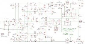
Here is a scan of a photo of the NAP 250 power amp stage from the chrome bumper age - without the regulators; for those who are new to this subject: The NAP250 had a fully regulated power supply individually for both channels:

Since Biguns schematic (in the basic outline) is closer to the original than the dreadful Avondale clone schematic, it is interesting how simple the original schematic is. (f.e. Instead of Avondales claims the input differential pair has no degeneration resistors, etc.)
It is definitely a tweaked design, which relates heavily to the exact parts (a perhaps matchings). Grounding is important, as always with Naim designs, but the exact PCB layout is simple and clear, without any magic track lenghth or the like.
I am referring to Biguns parts number here.
Please note the the main star ground is directly connected to the input ground (the green wire), no R2 (10R) here. The feedback ground and the input ground meet at a central (star) spot.
No antiparallel diodes across the feedback cap.
Exept of the input transistors (BC239 selected, usually marked) all other small signal transistors are e-line, that means ZTX753/653 for the drivers and - as far as I can remember - ZTX453 for the input CCS. Maybe that was another ZTX653, it seems not so critical here. Other Naim amps had different transistors here too (MPSA18 or 06).
The current control circuit uses ZTX453 etc. but is not used with Biguns circuit. I also always did the same - with some attention I did not need it. But the NAP250 amplifier was always also used with very difficult loads like Quad electrostatics and also could survive a short "short". Without the over-current circuit it wont.
The bias transistor was another ZTX653, which is not critical here. Interestingly this transistor is not mounted on the heatsink, as one should estimate, but right in the middle of the board, thus only coupled by the air temperature. But the closed non-ventilated Naim case was actually a big heatsink itself, so the inside temperature was pretty even, I guess.
The driver transistors were MJE340/350 as far as I can remember, but I will look into my texts tomorrow again.The baxandall diode is a normal 1N4148.
The power transistors are custom made for Naim (in those days by Semelab) and it is said that they are equivalent or similar to the BUV20, a fast switching transistor. Julian Vereker said in at least one interview, that he wanted a fast, but not necessary super linear transistor to work in a relativly low biased Class AB amp.
In the last remaining Naim clone I have I use the PT77 (by ST), a mil-spec version, originally made for the Cyrus 2. I do not recall the equivalent type at the moment.
The power emitter resistors, are Welwyn wirewound 0.22R, as wall as the 8R resistor for the output zobel. There is another output resistor with again 0.22R in line of the output, to linearize the damping factor for the full spectrum (at a lower but frequency constant level) and to isolate the output from the feedback line. This resistor is the most hated component and is omitted in most of the clones, but is mandatory for all Naim amps. (Maybe not until today, but today's version of these amps are not so interesting anymore...).
Instead of the output inductor Naim uses that 0.22R output resistor and recommended at least 2m lenghth of low capacitance loudspeaker cables. Their inductivity provided enough stabilty to the amp.
Interestingly all the resistors are pretty basic metal film types with 5% tolerance, except for the feedback resistors.
The caps are styroflex and tantalum beads, even the feedback cap and the input cap are polarized. The feedback cap had only 68uF.
I guess that the compensation R-C parts are tuned to the parts, they are different in other Naim amps, the Nait (1 and 2) did not have any. Of course all the Naim amps have the compensation R-C parts over the feedback resistor to shape the transient behaviour of the amp.
More later, also some more component values, if interested. It is late today here. I hope I can support this project. (Although I would never put those mosfets into the output line.)
Unfortunately, and I have said that already long ago here in one of the many Naim threads, I have never heard a Naim clone, which sounded better than the original ones. Not even mine.
I do not know why that is so, but I will stand corrected if that is not true and am looking forward to the first one which does. As an excuse I want to mention that I knew much less about amplifiers in the eighties than I know now (beeing involved in the NERO/Nytech resourrection...).