itsme -
The crossover performance is dependent on the load impedance, so you cannot measure the crossover slopes without the correct load.
If this was for a known set of drivers, you should use it with the drivers in place.
For more:
https://speakermakersjourney.blogspot.com/2016/12/crossover-basics-impedance.html
T/S parameters are pretty useless when it comes to crossover design. Apart the graph of the impedance (pretty easy to measure), what you need here is the FR of the driver on the baffle you're using, and this means you need a calibrated mic. Such a device doesn't cost an arm and a leg, but it can be questioned if it is a sensible cost for a one-shot project.
Ralf
Impedance can be easily measured this way: AudioBlog: A simple loudspeaker measurement jig for ARTA
I do have this spectrum analyzer with microphone, not sure how good BSR is but if not I have a new Audyssey setup mic from my new Marantz SR 7011 receiver. Would either one work? Thanks
Attachments
![IMG_0928[1].jpg](/community/data/attachments/547/547213-eee7dd141acde7b91a52170e8a3f8958.jpg?hash=7ufdFBrN57)
![IMG_0929[1].jpg](/community/data/attachments/547/547226-34f37bb835f16aece16e93f47efb4c24.jpg?hash=NPN7uDXxau)
![IMG_0930[1].jpg](/community/data/attachments/547/547244-7de2d5881911cb77e9444bd47ac8ca0e.jpg?hash=feLViBkRy3)
Itsme, you asked a simple question about how to hook up this crossover. The answer is +-- from your pictures.
Because it's a 4 element mid filter. Like this Troels Gravesen 3 way classic.
I really can't tell you what to modify to get it to work without seeing the whole circuit and the values. 4 ohm drivers will usually get different values from 8 ohm drivers. You usually need to adjust some loudness levels too.
itsme -
The crossover performance is dependent on the load impedance, so you cannot measure the crossover slopes without the correct load.
If this was for a known set of drivers, you should use it with the drivers in place.
For more:
https://speakermakersjourney.blogspot.com/2016/12/crossover-basics-impedance.html
Thanks Erik, The speaker makers journey is very helpful in understanding speaker filter basics. There is a lot I need to learn.
Itsme, you asked a simple question about how to hook up this crossover. The answer is +-- from your pictures.
Because it's a 4 element mid filter. Like this Troels Gravesen 3 way classic.
I really can't tell you what to modify to get it to work without seeing the whole circuit and the values. 4 ohm drivers will usually get different values from 8 ohm drivers. You usually need to adjust some loudness levels too.
Steve, When you refer to mid filter being 4 "element" Does element mean component? like 2 capacitors and 2 inductors? I'm not so good with terminology. Also using " +-- " Does this mean woofer normal, mid and tweeter inverted polarity? 😕 Thanks.
Yes.Steve, When you refer to mid filter being 4 "element" Does element mean component? like 2 capacitors and 2 inductors? I'm not so good with terminology. Also using " +-- " Does this mean woofer normal, mid and tweeter inverted polarity? 😕 Thanks.
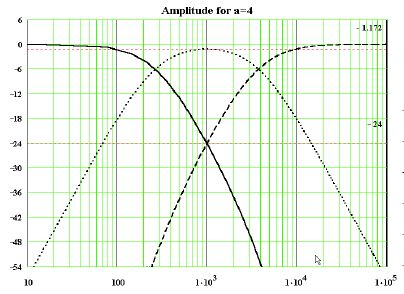
We usually aim for a smooth theoretical curve in three ways:
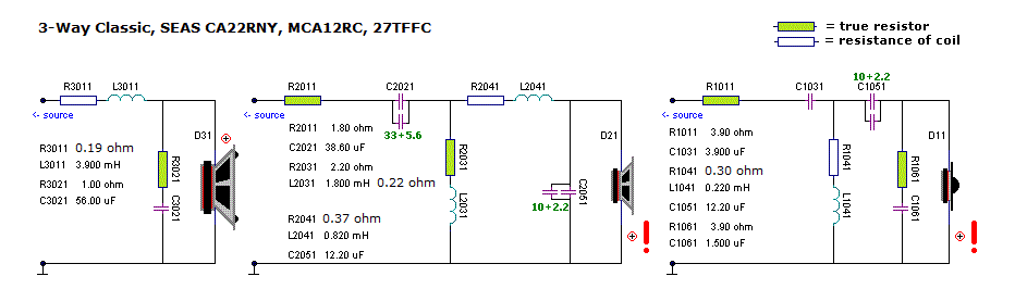
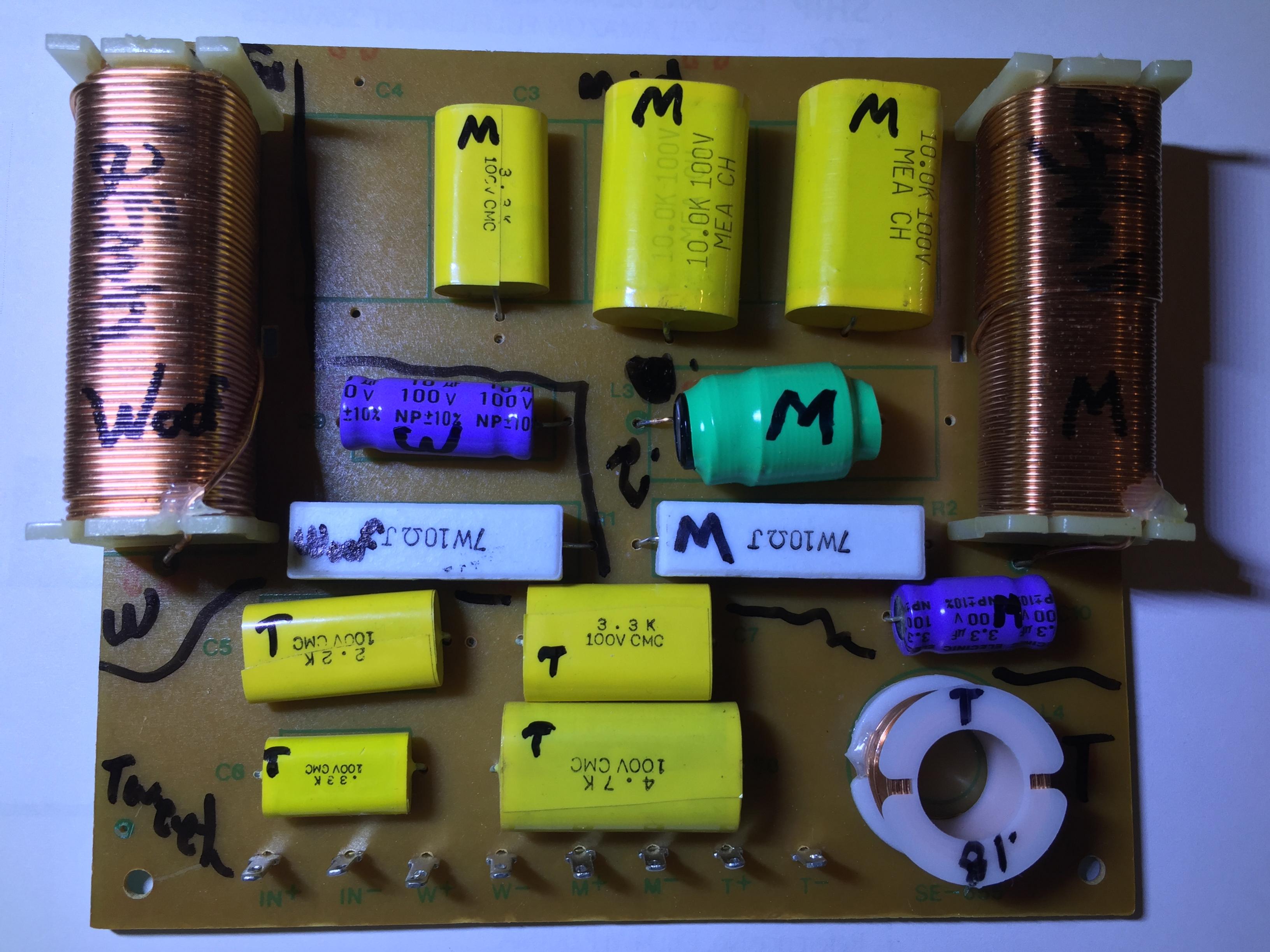
I'll repeat some previous advice. If I was looking at your speaker, I would say it's not wildly different form this Troels Gravesen SEAS 503 renovation.
SEAS Kit 503
Here's an example of another Troels filter we did a while back, I just suggested that with ANY similar drivers to his 3 way classic, the results wouldn't be too bad:
Now you might think that looks a bit rubbish, but actually, you only need to adjust the red resistors to get it flat. In other words, THAT one can be tuned by ear. The knack was finding a similar project to the drivers our member had.
http://www.diyaudio.com/forums/multi-way/301649-help-first-crossover-design-3-way-eton-speakers.html
Lot of work, this stuff! 😱
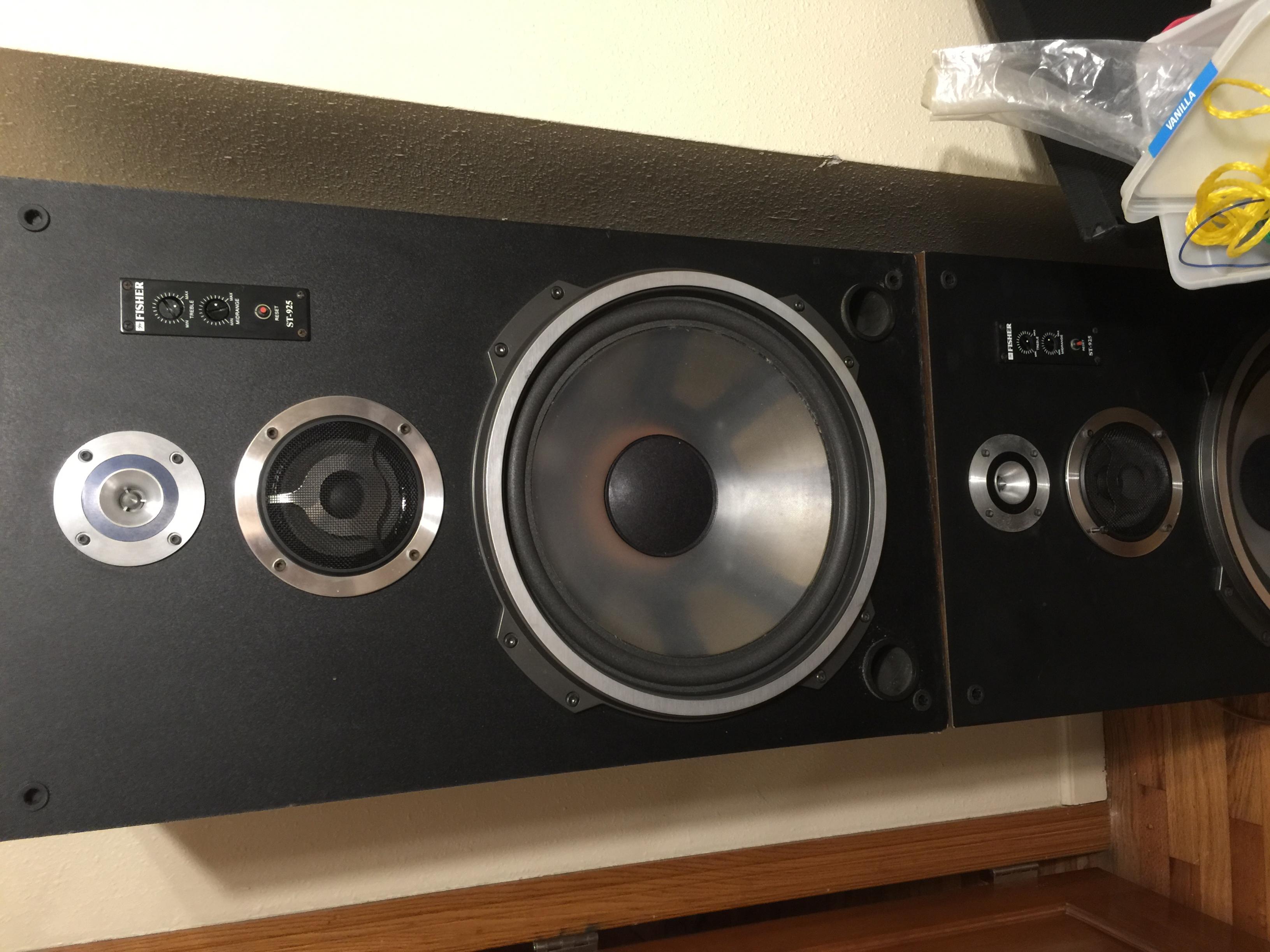
The original Fisher crossover.
Looks like you must have a mid filter and a tweeter filter there. I see 3 coils and 3 capacitors overall. So I would assume that is 4 elements mid and two elements tweeter.
We have unfiltered 15" 8 ohm polycone rolling off naturally at 1kHz.
4 ohm 4" mid coming in at 1kHz, and 4 ohm bullet tweeter coming in at 5.5kHz..
Also, and this is important, some level adjust attenuators on the mid and tweeter. These are effectively resistances. This might get round the 4 ohm issue, because these things can change things to nearer to 8 ohms. Who knows?
Your off-the-shelf crossover claims to be 600Hz/5kHz. Which is a good guess compared to the original. I'd like to know a bit more how the two attenuators are wired, but I think if you hook it up as suggested, +--, and fiddle with the two attenuators, it has a reasonable chance of working.
With the aid of that SEAS 503 article, you might get a clearer idea of what this crossover you have bought is. Personally, I would trace the schematic and sim it.
Last edited:
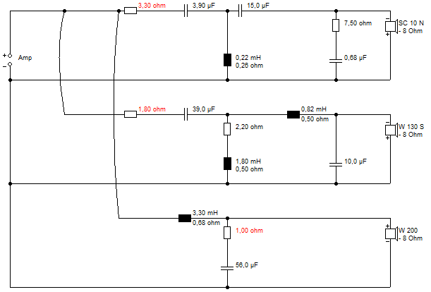
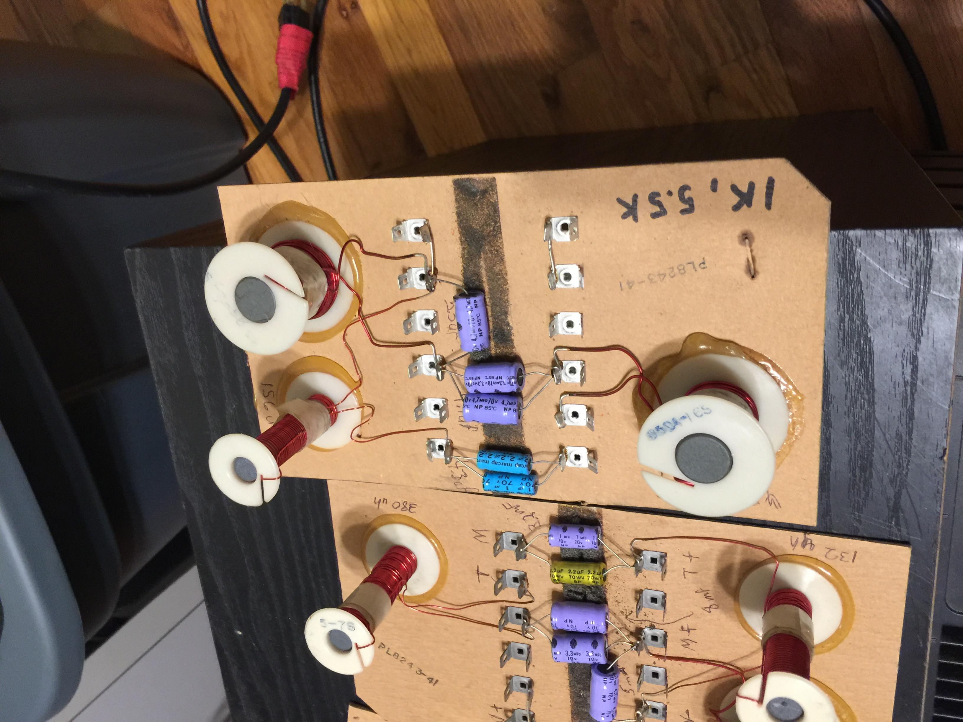
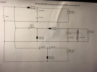
I just had a look at your filter:
I think it's the circuit below. We just need to add the attenuators. It seems to work as advertised. Impedance goes a bit low at mid frequency, so anything you can add to the 4 ohm mid is probably good. The tweeter filter doesn't mind a 4 ohm load.
I think it's the circuit below. We just need to add the attenuators. It seems to work as advertised. Impedance goes a bit low at mid frequency, so anything you can add to the 4 ohm mid is probably good. The tweeter filter doesn't mind a 4 ohm load.
Attachments
Last edited:
Lot of work, this stuff! 😱
The original Fisher crossover.
Looks like you must have a mid filter and a tweeter filter there. I see 3 coils and 3 capacitors overall. So I would assume that is 4 elements mid and two elements tweeter.
Yes, that is correct
We have unfiltered 15" 8 ohm polycone rolling off naturally at 1kHz.
4 ohm 4" mid coming in at 1kHz, and 4 ohm bullet tweeter coming in at 5.5kHz..
Now the 1khz and 5.5khz is probably not correct because I measured with frequency generator connected to inputs of crossover and oscilloscope connected to midrange and tweeter outputs "No Load" . this was before I knew about hooking up a load resister in place of drivers.
Also, and this is important, some level adjust attenuators on the mid and tweeter. These are effectively resistances. This might get round the 4 ohm issue, because these things can change things to nearer to 8 ohms. Who knows?
The level adjustments were wired from positive speaker lead to both rheostats and then output of rheostat to each driver, tweeter inverted. each stat is violet brand 20 ohm. (picture below)
Your off-the-shelf crossover claims to be 600Hz/5kHz. Which is a good guess compared to the original. I'd like to know a bit more how the two attenuators are wired, but I think if you hook it up as suggested, +--, and fiddle with the two attenuators, it has a reasonable chance of working.
With the aid of that SEAS 503 article, you might get a clearer idea of what this crossover you have bought is. Personally, I would trace the schematic and sim it.
I will try and trace a schematic out for it.
I am still trying to figure out this software "REW" so I can measure the drivers and box "Fr" and impedence to make this easier and more accurate.
Attachments
![IMG_0933[1].jpg](/community/data/attachments/547/547412-39b1fd7c6ff9d594228fa96bf210da49.jpg?hash=ObH9fG_51Z)
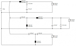
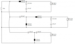
I've already had a stab at the filter:

Can't think what else it could be. Have a look. If you read back, you'll find some more observations from me. The 1kHz/5kHz XOver is not unreasonable for a 15" bass and bullet tweeter.
Must go now. 🙂
Can't think what else it could be. Have a look. If you read back, you'll find some more observations from me. The 1kHz/5kHz XOver is not unreasonable for a 15" bass and bullet tweeter.
Must go now. 🙂
Oh yeah, 4 Ω speakers produce more output than 8Ω speakers, given the same amplitude signal.
That's why at Fisher they put those 4 Ω drivers to mate with the woofer - the G-normous Sd moves lots of air particles thus contributing to produce substantial SPL levels.
That's why I suggested to look for some midrange drivers with 8Ω coils with a higher Sd than the original midrange. It applies also to the tweeter.
Dunno why Steve makes acceptable the fact that a X-O calculated for 8 Ω driver might work with halved load !?!
Oh yeah, 4 Ω speakers produce more output than 8Ω speakers, given the same amplitude signal.
That's why at Fisher they put those 4 Ω drivers to mate with the woofer - the G-normous Sd moves lots of air particles thus contributing to produce substantial SPL levels.
That's why I suggested to look for some midrange drivers with 8Ω coils with a higher Sd than the original midrange. It applies also to the tweeter.
Dunno why Steve makes acceptable the fact that a X-O calculated for 8 Ω driver might work with halved load !?!
I agree with u on going to 8 ohm mid and tweets and Steve did too but thought I could get by with these because of the mid and tweet having the 20 ohm rheostats on speaker cabinet.
😕😕
I would ditch the rheostats anyway
😛
Or are those L-pads ? ( double rheostats in one body to achieve constant impedance)
Once the outputs are dialed in by the means of resistors, i.e. when the sound balance is complete, there is no need to change it.
I would avoid the crossover to be inside the box. Bring the three couples of wires outside the box and listen.
Actually that is a great idea installing the crossover outside the box, glad you mentioned that. So you think the L-pads will degrade sound quality or just cause more problems with impedance? Also would you have any suggestions on decent replacements for 6" mids and 3" tweeters?
Okay, I ended up ordering Dayton Audio DC28f-8 tweeter's and Pyle PPA6 6 inch mids and Pyle PPA15 woofers all 8 ohm. So not sure these crossovers will still work seeing that the tweeters Fs is around 1,800 Hz. So may have to build new xovers. Any ideas?
I do have this spectrum analyzer with microphone, not sure how good BSR is but if not I have a new Audyssey setup mic from my new Marantz SR 7011 receiver. Would either one work? Thanks
Don't obsess over the microphone. For an amateur almost any mic will be "good enough". Only when you start to get to caring about a few dB at 10 kHz is the mics quality going to be an issue. For crossover work it is going to be fine.
This project is turning into a complete muddle IMO. Sorry. 😱
We now have 3 new random drivers to deal with because you were impetuous, and it's essentially a new speaker. We have a new crossover that may or may not work. The bass loading may be different, reflex or closed box.
I have updated the schematic based on your more precise evaluation. I'm still not sure where the rheostats are in the circuit.
To your credit, Itsme, you seem to be learning fast, have a little electrical savvy, and are willing to roll your sleeves up.
All this talk of problem 4 ohms or 8 ohms drivers was something that could be dealt with. In fact the off-the-shelf filter is quite comfortable with a 4 ohm tweeter, and we could do something about the 4 ohm midrange in all likelyhood.
A 3 way is a skilled project. You need drivers that play nicely together and the right idea. SEAS Kit 503
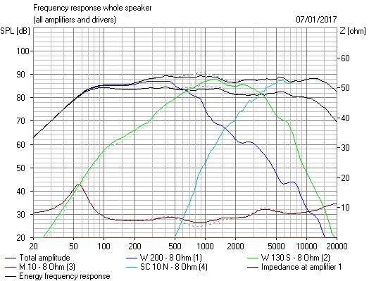
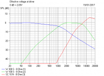
Here's a sim with a 6" mid and a regular sort of 1" tweeter. I don't have any 15" basses to hand, polycone or paper, so I'm limited in what I can do here without a huge investment of time in importing FRD and ZMA files for Pyle drivers. There are all sorts of other details to take in too.
I really don't know where we go from here. IMO, this is a back to the drawing-board moment. And I wouldn't be too reliant on help from most people here, who get notoriously vague when it comes to actual practical detail, IME. 🙁
We now have 3 new random drivers to deal with because you were impetuous, and it's essentially a new speaker. We have a new crossover that may or may not work. The bass loading may be different, reflex or closed box.
I have updated the schematic based on your more precise evaluation. I'm still not sure where the rheostats are in the circuit.
To your credit, Itsme, you seem to be learning fast, have a little electrical savvy, and are willing to roll your sleeves up.
All this talk of problem 4 ohms or 8 ohms drivers was something that could be dealt with. In fact the off-the-shelf filter is quite comfortable with a 4 ohm tweeter, and we could do something about the 4 ohm midrange in all likelyhood.
A 3 way is a skilled project. You need drivers that play nicely together and the right idea. SEAS Kit 503
Here's a sim with a 6" mid and a regular sort of 1" tweeter. I don't have any 15" basses to hand, polycone or paper, so I'm limited in what I can do here without a huge investment of time in importing FRD and ZMA files for Pyle drivers. There are all sorts of other details to take in too.
I really don't know where we go from here. IMO, this is a back to the drawing-board moment. And I wouldn't be too reliant on help from most people here, who get notoriously vague when it comes to actual practical detail, IME. 🙁
Attachments

- Status
- Not open for further replies.
- Home
- Loudspeakers
- Multi-Way
- Need help with crossover type!