I have my circuit for a mosfet voltage regulator for the screens of 7591s in my Eico ST-70. I'm in the planning phase on what exactly to do with this amp. As I mentioned in another thread, this amp is missing the cover grill, and has been modified a bit. It's no beauty queen and is definitely not a restore project.
So one of my own options is to move the trannies to my own made chassis and simplify the topology. Keep the basic power amp with one gain stage in the front with no EQ. In scouring this and other forums for info and ideas, I stumbled on the mosfet concertina phase inverter. This appears to be the best of both worlds, but due to my limited knowledge I have no way of knowing if that is true.
Please tell me if the following is correct.
1. A gain stage should be direct coupled to the mosfet PI for the feedback loop to be implemented. The mosfet will want to see 25% of the supply voltage at the gate for best output swing. The challenge will be to find a tube that will be very linear in operating conditions that will result in about 100v at the plate, given the mosfet PI has a supply voltage of 400v.
2. Each mosfet PI will probably be eating up 5 to 10 mA of current. The gain stage that is directly coupled might be the same. So we could easily have 30 to 40 mA of current needed. That might be a problem for the stock power transformer, I don't know. 7591 tubes don't need much, so maybe I'm over estimating.
3. The screen regulator circuit comes right off the first input cap, so I thought a good idea might be to use a choke after that with a cap for the mosfet PI. The choke could be higher resistance than the usual screen supply choke since we are actually trying to drop some voltage. Dropping 50 to 70 volts with about 40 mA gives a resistance of 1200 to 1700 ohms with a power dissipation of about 3 watts. Edcor has an open frame choke with 15H, 75mA and R of 347 for just under 30$.
These are the basic thoughts I have right now. It seems to have a lot of advantages. Matching up load resistors is something even I could do. No cathode to heater voltage to worry about. I read that thread over on AA that Eli Duttman linked from another thread here in DIY Audio. There's something about the mosfet that needs a slightly different voltage on the source as compared to the drain, so someone that made this put a variable resistor to dial it in for balanced output (I'm assuming with the use of a scope). I have to look more into that.
Do I have the basics correct here? It seems like this could be a sort of modern, "ultimate" Mullard 5-20 type of power amp. Am I missing something?
Not sure where the 25% came from, the PI swing will be quite asymmetrical. If you need this sort of voltage swing or want the headroom as a matter of design approach you will want to raise to the plate voltage a bit on the first stage to optimize headroom. (Say 130V with a 400V PI supply)
Not sure where the 25% came from, the PI swing will be quite asymmetrical. If you need this sort of voltage swing or want the headroom as a matter of design approach you will want to raise to the plate voltage a bit on the first stage to optimize headroom. (Say 130V with a 400V PI supply)
The 25%? Many years ago I was told by someone who knew way more than me that the most symmetric output swing you could get from a concertina was had by making the grid see one third of the supply voltage. Now it seems every source I find says it is really 25% for reasons that are not given or are not understood by me. Mostly they are not given. I will have to look into this part of it more so I understand what's going on.
I have confirmed by experiment that 25~30% yields maximum undistorted output swing. This work was done with a 6GH8 and 300V B+ supply.
> The 25%? ... told ... grid see one third.... Now it seems
For a perfect device and infinitely light loading, 25% is optimum. Bottom swings 1%-49%, top swings 51%-99%.
Resistance coupled means you never swing to the 1% or 99% points.
If the device has resistance (vacuum tube), you never swing hear the 49% and 51% points.
33% may be a fine initial target for a basic tube cathodyne.
If you can do basic voltage-dividers, you can easily work this out on a matchbook. If the cathode (Source) sits at 100V, with 100K DC load, and 200K AC load from the next tube's grid bias, it can only swing-down 67% or to 33V. If the device has 33K minimum internal impedance, it can only swing-up a similar amount, to 167V.
This is NOT an optimum for the stage before it. Which is usually more critical than the heavily degenerated cathodyne.
> gain stage should be direct coupled to the mosfet PI for the feedback loop
R-C coupling adds a bass-cut and complicates stability. However, MOSFET Gate resistor can be 10Meg or more. An affordable 0.1uF cap gets you to 0.2Hz. If even this is not deep enough, you can boot-strap (but be aware the loading unbalances the cathodyne). Alternatively you can 2-pole it: let driver run 50%, two 10Meg resistors gets cathodyne gate to 25%, and a 0.1uF cap gives 100% gain above 0.2Hz and 50% gain 0.1Hz to DC, phase shift very teeny.
And if you have 400V supply but only need 10V swing to the next stage (EL84, or a push-pull voltage amp) then none of this is real critical. 7591 are not real pigs for drive. Likely if you can feed the cathodyne "most" of what you give the 7591 screens, it will not strain. That's why audio power tubes have Mu(g2) of 10 or more, whereas Mu(g2) like 5 or 4 would pass bigger currents (and need huger grid drive).
25% gives maximum output swing.
30% gives better distortion as the tube is operating in a more linear portion of the curves, however the 100% feedback may make this moot.
30% gives better distortion as the tube is operating in a more linear portion of the curves, however the 100% feedback may make this moot.
See Jeff Yourison's 6Y6 amp for a successful implementation of a MOSFET "concertina" phase splitter.
When B+ volts are in short supply, the FET has a distinct advantage over a triode.
When B+ volts are in short supply, the FET has a distinct advantage over a triode.
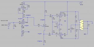
I've just completed a 7591 amp with DC coupled mosfet split load phase inverter. I didn't start out with the intention of using a mosfet, instead I was going to use either a pentode/triode or dual triode (I only had 1 socket available for combined VA and PI). I needed a decent amount of gain to allow enough NFB with the pentode output stage. The classic approach is to use a pentode for voltage amplification which provides plenty of gain and can operate well at the lowish anode voltages required for DC coupling to the PI. I wanted to use a triode instead but it was difficult to find something with high mu that could run at a sensible operating point with low anode voltage.
SY used a 12AT7/ECC81 in his Red Light District which would have been OK, but I wanted to try something else. A triode connected EF184 was what I ended up with (low rp allows reasonable current at low anode voltage while maintaining a cathode voltage of around 2V). But that meant I didn't have a socket available for the PI.
So I tried a mosfet (I used a FQP2N60) and it worked well. You don't need much voltage across the mosfet, just enough to ensure the Drain-Source voltage remains above about 20V at minimum to keep Crss in the linear region. You also don't need much current when driving pentodes. Higher current gives higher gm but a mosfet has plenty even at low currents. A mosfet thus allows more leeway in choosing the operating point for the voltage amplifier. Don't forget to add a 12V zener between gate-source or otherwise you will destroy the mosfet on start-up (so I found...).
Schematic below. Actual amp has voltage regulated screen supplies plus additional components for feedback stability.
Attachments

- Status
- Not open for further replies.
- Home
- Amplifiers
- Tubes / Valves
- Mosfet concertina - a better, more simple to design power amp?