I'm just finalising the power supply for a stereo power amp that I am building.
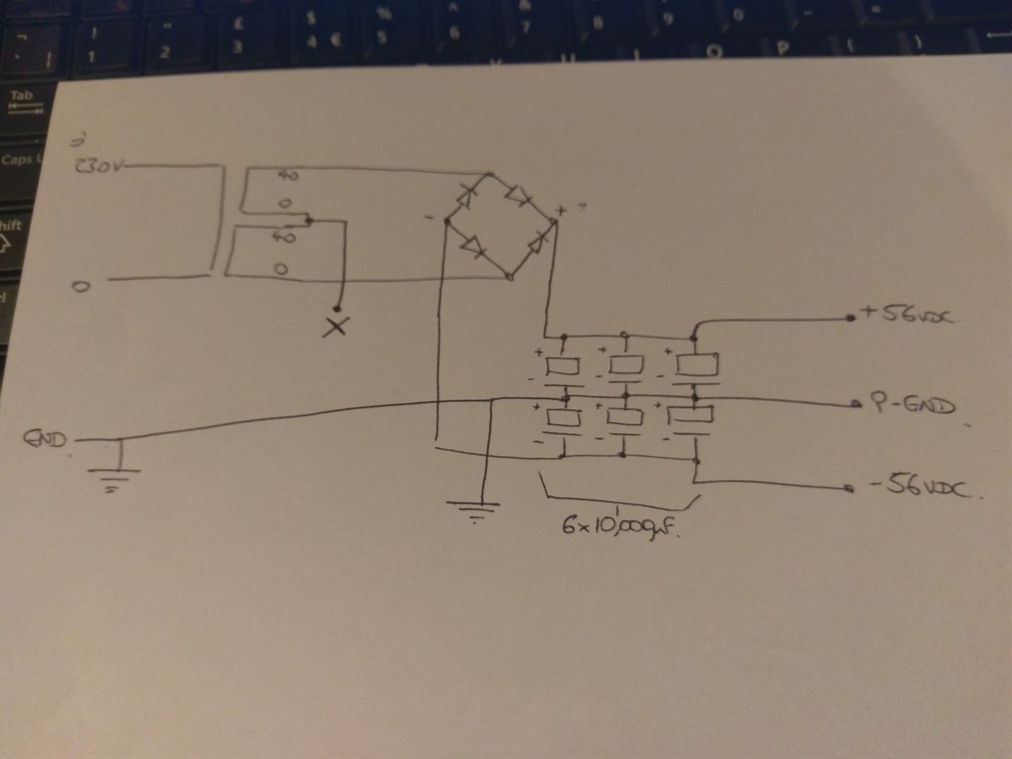
I have a dual 0-40 secondary transformer, I've linked it up as shown, but should I be connecting that link (marked X on my dodgy sketch), which is essentially the center tap, back to the main power ground point?
Sorry for the dumb.... I'm clearly having a blonde moment 😛
I have a dual 0-40 secondary transformer, I've linked it up as shown, but should I be connecting that link (marked X on my dodgy sketch), which is essentially the center tap, back to the main power ground point?
Sorry for the dumb.... I'm clearly having a blonde moment 😛


No, not really
The central 0 volt point is the junction of the 2 RHS caps and this is connected to both the amplifier and the main ground point on the mains inlet connector or chassis close to that - the 'X' is connected to the junction of the first 2 caps on the LHS and to the central earth bus bar on the capacitors, not a separate one to ground
Incidentally, you can add a small value resistor between the first pair of caps on each rail so it resembles a C-R-CC on each rail - value generally about of 0.1
Ohm - this reduces the amount of voltage ripple on each rail by a big amount
As you rail voltages are given as +/- 56V dc (40V ac secondaries?) I suggest increase voltage rating of the caps to be the next voltage increment above the 63 volt like 80V dc, for example - the reason why is that (guessing a bit) that this is for a classAB amp and at low power loads, and maybe high mains voltages, the rail voltage can increase quite a bit - 63V ones probably okay in the short term but if the option is available and the budget okay, suggest use the higher voltage ones.
Oh yes, try to use either a really good quality block bridge or discrete diodes - it makes a huge difference to final sound - also, again be generous with diode voltage ratings - 200volt ones okay
And don't forget that the power supply caps ARE part of the power amps circuit (in series with the load return from the speakers) so effectively the quality of these will directly contribute to the final sound of your amp - many people forget this just to save some $s.
All the best ...
Oh yes, forgot - have a look at the way the power supply is shown in any of the First Watt amplifiers in the First Watt website - they are for the class A amplifiers but the same rules apply
Thanks 🙂 so I was right in thinking it should be grounded, it would be to the central bus link on the caps. I'll add another wire in for that 🙂
The caps are all rated at 80V and I do have 0.1ohm 5W resitors rather than wire links on each rail. The bridge is a 35A/400V block type.
Here's what it currently looks like, still a lot to finish off.
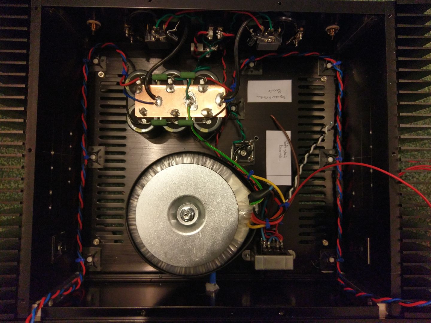
And yes it's AB design - lateral MOSFET
The caps are all rated at 80V and I do have 0.1ohm 5W resitors rather than wire links on each rail. The bridge is a 35A/400V block type.
Here's what it currently looks like, still a lot to finish off.
And yes it's AB design - lateral MOSFET
The Centre tap must be connected to the first junction of the smoothing capacitors.
That group of cables from transformer to rectifier must be low loop area. Twisted triplet is best.
The group of cables from the rectifier to the smoothing capacitor bank must be low loop area. Twisted triplet is best.
Do not braid instead of twisted. Braiding increases the loop area and thus increases the emi.
the centre tap goes to the capacitors.
The plate between the smoothing capacitor bank has 6 solder pads for the 6 capacitor pins.
There are three other solder pads with maybe 6 other wires emanating. These 6 wires will all be at different voltages.
Why are you sending all these different voltages to other modules in the amplifier?
That group of cables from transformer to rectifier must be low loop area. Twisted triplet is best.
The group of cables from the rectifier to the smoothing capacitor bank must be low loop area. Twisted triplet is best.
Do not braid instead of twisted. Braiding increases the loop area and thus increases the emi.
No.so I was right in thinking it should be grounded
the centre tap goes to the capacitors.
The plate between the smoothing capacitor bank has 6 solder pads for the 6 capacitor pins.
There are three other solder pads with maybe 6 other wires emanating. These 6 wires will all be at different voltages.
Why are you sending all these different voltages to other modules in the amplifier?
Last edited:
Yes 40v AC through a full wave bridge is
40 X 1.414 = 56.25
assuming the mains is the correct voltage but allowing for a 10% rise in supply voltage, this could be as high as 62volts off load. A bit too close for comfort.
Why such a high capacity? 30,000uF is an awful lot!
In my opinion, use the centre point of all smoothing capacitors as a common ground point and always return the loud speaker to that point to reduce spurious current loads elsewhere in your circuit. That will take care of any hum.
No commercial producers of quality amplifiers use 0R1 resistors between the smoothing caps. If it were an advantage, don't you think Sony, Sharp, Philips, Marantz, Crown, JVC etc would? No advantage there, just a few millivolts of ripple and something else to go wrong.
There is no benefit to twist DC wires. It increases the length and any transmission of EMF. Keep them straight, near the chassis and together.
No.
the centre tap goes to the capacitors.
The plate between the smoothing capacitor bank has 6 solder pads for the 6 capacitor pins.
There are three other solder pads with maybe 6 other wires emanating. These 6 wires will all be at different voltages.
Why are you sending all these different voltages to other modules in the amplifier?
But the plate between the capacitors is ground, so effectively the centre tap is ground?
Where would you suggest I connect them to? The wires from it are:
2x Speaker return
2x Power ground to amplifier modules
1x safety earth to chassis and 3rd pin of IEC connector
1x safety earth to torroid
It's 1.5mm thick copper plate - I thought that would be a fairly effective star ground point...?
Yes 40v AC through a full wave bridge is
40 X 1.414 = 56.25
assuming the mains is the correct voltage but allowing for a 10% rise in supply voltage, this could be as high as 62volts off load. A bit too close for comfort.
Why such a high capacity? 30,000uF is an awful lot!
In my opinion, use the centre point of all smoothing capacitors as a common ground point and always return the loud speaker to that point to reduce spurious current loads elsewhere in your circuit. That will take care of any hum.
No commercial producers of quality amplifiers use 0R1 resistors between the smoothing caps. If it were an advantage, don't you think Sony, Sharp, Philips, Marantz, Crown, JVC etc would? No advantage there, just a few millivolts of ripple and something else to go wrong.
It was simply the recommendation for the amp's I am building by the designer. The caps are all rated at 80V.
All ground points for the whole amp go back to the smoothing caps.
There is no benefit to twist DC wires. It increases the length and any transmission of EMF. Keep them straight, near the chassis and together.
Duly noted.... thank you 😀
It is not ground. It is a conductor passing pulsing currents between the centre tap and the capacitor pins. All the different parts of that conductor are at different voltages.But the plate between the capacitors is ground, so effectively the centre tap is ground?
take each to the Main Audio Ground (MAG) for that channelWhere would you suggest I connect them to? The wires from it are:
2x Speaker return
The +ve, -ve and zero volts go as a twisted triplet to one amplifier. and a second twisted triplet to the second amplifier.2x Power ground to amplifier modules
The PE connection from the IEC socket goes to Chassis beside the IEC connector.1x safety earth to chassis and 3rd pin of IEC connector
The Fault current route from MAG to Chassis should be short and at the MAG. This is to comply with "all exposed conductive parts should be connected to the protected chassis". This connection should not be taken across, or around, an enclosure to reach some remote chassis connection. Keep it short.
What safety Earth for the toroid? Are you referring to an electrostatic screen between the primary and secondary?1x safety earth to torroid
The pulsing currents in the rectifier circuit can be 10times the AC rms current equivalent draw. If you measure a 1Arms when the amplifier is playing loud then the pulses can exceed 10Apk. These pulses will create voltage drops acrosss any impedance in their path. One cannot create zero impedance !It's 1.5mm thick copper plate - I thought that would be a fairly effective star ground point...?
Last edited:
There is no benefit to twist DC wires. It increases the length and any transmission of EMF. Keep them straight, near the chassis and together.
Which wires was he referring to that ONLY carry constant non changing DC?Duly noted.... thank you 😀
DC is Direct Current. DC current can and does vary.
Any changing current flowing along a conductor emits emi. Even when that is a changing DC current.
That's why the Flow and Return PAIR should have a low loop area: to minimise emi. Twisting improves the attenuation of the emitted emi.
OK.... I think this is semantics... and it's actually just plain confusing.
The plate between the capactors is ultimately connected to the IEC earth pin, so it is 0v/ground/earth. Correct?
To answer each point in turn:
The MAG and speaker return are connected to the same point on the copper plate for each channel.
The +, - and zero/ground are the twisted triplet running along each side of the case - 1 set for each amplifier.
The earth pin of the IEC is connected to the chassis at the IEC. There is then a short wire to the plate between the caps, both of these wires are <1.5" total length. All 'safety' earths are connected to the central point on the plate. The MAG and speaker returns are at either end.
My torroid has an earth cable - therefore it's connected back to the main ground plate at the caps.
Last edited:
................I have a dual 0-40 secondary transformer, I've linked it up as shown, but should I be connecting that link (marked X on my dodgy sketch), which is essentially the center tap, back to the main power ground point?................
Interpret that as semantics if you want.The Centre tap must be connected to the first junction of the smoothing capacitors................
Bad idea. You have lost control of where the currents go. A simple copper wire (or PCB trace) bus is better. One end goes to the secondary CT. The other end goes to the circuitry, and also may have the speaker returns. Along the bus go the PSU capacitor joins.flak monkey said:It's 1.5mm thick copper plate - I thought that would be a fairly effective star ground point...?
It is not as simple as that. Two points connected together only have the same potential if there are no currents flowing and no AC magnetic fields around.The plate between the capactors is ultimately connected to the IEC earth pin, so it is 0v/ground/earth. Correct?
Might be better to connect the toroid screen to chassis. That way you are not injecting mains noise straight into your signal ground.My torroid has an earth cable - therefore it's connected back to the main ground plate at the caps.
All safety earths (not sure what you mean by this) should go to the chassis.All 'safety' earths are connected to the central point on the plate.
I recommend you do some reading on grounding.
Last edited:
OK, I was simply following the recommendations from the designer of the amplifier circuits when I built this.
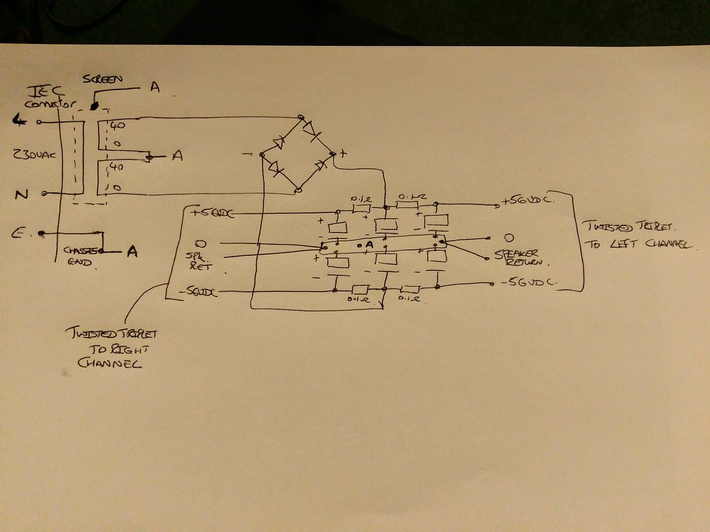
Excuse the slightly scrappy sketch, but this is what the overall scheme looks like.
All those labelled with 'A' connect to the central point on the copper plate also labelled 'A'. When I refer to safety earth I refer specifically to the chassis earth.
I understand the comment about separating out the torroid screen, and I can move that relatively easily to the chassis ground point.
There is no benefit to twist DC wires. It increases the length and any transmission of EMF. Keep them straight, near the chassis and together.
These wires carry pulses of current and there is nothing "DC" about that... Transformer, rectifier, and smoothing caps are all seeing very irregular current flow and all wires in between should be routed to have minimum loop area to keep EMF radiation and amplifier hum to a minimum, if not inaudible, level.
- Status
- Not open for further replies.
- Home
- Amplifiers
- Power Supplies
- Dumb moment - grounding center tap