just a silly question... post 15272, second picture. i connected the right and left side of the PSU board with 4 jumpers. actually there is a very small loop now, could that be the problem?
next:
insert a long interconnect into one input and the dummy plug in the second.
Is there H+N.
Now short the remote end of the long interconnect and measure again.
Swap the dummy with the long. Measure with open end and with shorted end.
Are all four results the same as the dummy plugs only? 0.0mVac?
Now repeat with a long interconnect in both inputs. First open ends and then shorted ends. two more results
and finally with the shorted ends , touch the two remote barrels together and measure this final H+N.
next:
insert a long interconnect into one input and the dummy plug in the second.
Is there H+N.
Now short the remote end of the long interconnect and measure again.
Swap the dummy with the long. Measure with open end and with shorted end.
Are all four results the same as the dummy plugs only? 0.0mVac?
Now repeat with a long interconnect in both inputs. First open ends and then shorted ends. two more results
and finally with the shorted ends , touch the two remote barrels together and measure this final H+N.
Ok, here we go:
D...Dummy, L...long interconnect, D+L...Dummy with a long interconnect
X... i can hear a hum, O.... I can not hear a hum
i will right it that way:
D - D: O - O
meaning: Dummy plug left, Dummy plug right: cant hear hear a hum left, cant hear a hum right.
those are my results:
L - D: X - O
L+D - D: O - O
D - L: O - X
D - L+D: O - O
L - L: X - X
L + D - L + D: O - O
L+D - L: O - X
L - L+D: X - O
I always measured 0.0mVac, also in the case when i heard a hum. But I have to admit, the hum was really quiet, but still to hear when my ear is close to the speaker. Those results show that always when I use a long interconnect without the dummy at the end I can hear a hum.
I am not sure that I understood what you meant. What I have done is using a long interconnect on both inputs and put them together at the open endings, thus connecting input-L with input-R and input-gnd-L with input-gnd-R. This created the loudest hum which I was able to measure resulting in 0.5mVac left and 0.4mVac right.finally with the shorted ends , touch the two remote barrels together and measure this final H+N.
I also measured long interconnect and dummy on both sides, and then I connected those two, thus again a loop, but signal-inputs are connected to gnd. Same result: I can hear a hum on both sides and I can measure 0.5mVac and 0.4mVac.
Happy new year by the way!
0.0mVac is completely inaudible with normal speaker sensitivity. I don't understand how you can hear any hum with voltage readings of <0.1mVacI always measured 0.0mVac, also in the case when i heard a hum.
This last result is telling us that the increase in H+N voltage from 0.0mVac to 0.4mVac is due to the loop current passing around the connected Left and Right signal returns.But I have to admit, the hum was really quiet, but still to hear when my ear is close to the speaker. ............................
I also measured long interconnect and dummy on both sides, and then I connected those two, thus again a loop, but signal-inputs are connected to gnd. Same result: I can hear a hum on both sides and I can measure 0.5mVac and 0.4mVac...........
This is what HBRR + HBRL is intended to attenuate.
You have inserted some resistance in the wrong position.
Look again at the D.Joffe paper and work out what you have done incorrectly.
0.0mVac is completely inaudible with normal speaker sensitivity. I don't understand how you can hear any hum with voltage readings of <0.1mVac
It's nearly not noticeable, but I also asked my girlfriend now, she can hear it as well. When I use the DMM and measure, at the beginning it shows 0.2mVac but when I stay there it goes down to 0.0mVac...
At the moment I have no resistors added, but I will try those measures again with 10Ohms HBRR and HBRL.This last result is telling us that the increase in H+N voltage from 0.0mVac to 0.4mVac is due to the loop current passing around the connected Left and Right signal returns.
This is what HBRR + HBRL is intended to attenuate.
You have inserted some resistance in the wrong position.
Look again at the D.Joffe paper and work out what you have done incorrectly.
Could this be a broken DMM?It's nearly not noticeable, but I also asked my girlfriend now, she can hear it as well. When I use the DMM and measure, at the beginning it shows 0.2mVac but when I stay there it goes down to 0.0mVac...
0.2mVac is just about audible on 88db speakers
So are you back to the original build with no added resistors in the input cables?At the moment I have no resistors added, but I will try those measures again with 10Ohms HBRR and HBRL.
0.2mVac is 83dB below 1W.
If you move in to 0.1m that gets the SPL up by ~ 20db from 5dB above audibility to ~ 25dB above audibility.
Move in to 0.02m and you may get another increase of a few dB, so that you can hear that 0.2mVac. I don't think I could hear that.
I think I can just about hear 0.3mVac with an ear very close to the speaker cone.
Last edited:
So are you back to the original build with no added resistors in the input cables?
Yes, I the original version. I wanted to use the amp yesterday evening, and as the original version was the most quiet one i went back to the original.
0.2mVac is 83dB below 1W.
If you move in to 0.1m that gets the SPL up by ~ 20db from 5dB above audibility to ~ 25dB above audibility.
Move in to 0.02m and you may get another increase of a few dB, so that you can hear that 0.2mVac. I don't think I could hear that.
I think I can just about hear 0.3mVac with an ear very close to the speaker cone.
🙁, I hope not that the DMM is broken, I can only tell what I hear and see on the screen of the DMM. Hm, so do you still think that the issue comes from a cross channel ground loop?
If you are sure there is a big increase in hum with the connected signal returns between the two channels, then it convinces me that this is the biggest problem. Adopt the HBRR+HBRL
If you are sure that the long interconnects with the shorted remote ends is completely silent, then that points to the internal wiring being correct.
It seems that it's the PCB designer, who should have told every builder that he designed the layout to suit mono-blocks only, who made the mistake.
Stereo/multi-channel amplifiers need a different arrangement compared to mono-block. But be consoled, 90% of amp layout designers make the same mistake !
It's only in the last couple of years that a few "wide awake" Members here have adopted the HBRR+HBRL solution.
I have not seen any other solution that effectively attenuates the loop/interference current.
Last edited:
If you are sure there is a big increase in hum with the connected signal returns between the two channels, then it convinces me that this is the biggest problem. Adopt the HBRR+HBRL
If you are sure that the long interconnects with the shorted remote ends is completely silent, then that points to the internal wiring being correct.
It seems that it's the PCB designer, who should have told every builder that he designed the layout to suit mono-blocks only, who made the mistake.
Stereo/multi-channel amplifiers need a different arrangement compared to mono-block. But be consoled, 90% of amp layout designers make the same mistake !
It's only in the last couple of years that a few "wide awake" Members here have adopted the HBRR+HBRL solution.
I have not seen any other solution that effectively attenuates the loop/interference current.
I understand, too bad, i should have built mono-blocks then... Anyway, i will give it another try with the 10R resistors. It seems like someone had the same problem (post 14651), but I think now solution was found...
I did the last test (long interconnects with dummys and put together) with one hum breaking resistor, 12R (so not for both channels...).
The hum gets louder and i measure 1mVac at the output!
I really don't now whats happening, the resistor must be at the wrong spot, but I can't see why.

that's what i did. As suggested the input circuit must be complete, thus i removed R2 from the board, and soldered it as in the picture, furthermore i added the HBR.
this is the backside of the pcb

The hum gets louder and i measure 1mVac at the output!
I really don't now whats happening, the resistor must be at the wrong spot, but I can't see why.
that's what i did. As suggested the input circuit must be complete, thus i removed R2 from the board, and soldered it as in the picture, furthermore i added the HBR.
this is the backside of the pcb
So, somebody here who can help me or has further more ideas where i have to place the hum breaking resistors?? The amp sounds already amazing, and I only hear the hum when my ears a very close to the speakers, but still, this drives me crazy, especially that nothing what I do has an impact on this 🙁
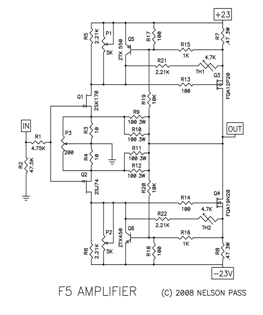
F5 - smoked R13
Hi all, after nearly four years of regular use, my F5 let out a soft, high-pitched hum on startup, then let the smoke out. I immediately turned it off and found that R13 burned up. Nothing else is visually wrong.
The only recent change made was a speaker protector board that was added a few days ago. It ran just fine for several hours of use after the board was added.
I'd appreciate troubleshooting tips from the experts here -- thanks. 🙁
R13? The 100R mosfet gate resistor?
pull out all semis and test them
while they're out , check resistors
replace what's burned , repeat proper biasing procedure
check for burs on heatsink , be sure when tightening mosfets to hsink
- easiest way to fix the amp is - take it and fix it

while they're out , check resistors
replace what's burned , repeat proper biasing procedure
check for burs on heatsink , be sure when tightening mosfets to hsink
- easiest way to fix the amp is - take it and fix it
well , you have 2+2 important transistors per channel , and +2 not so necessary ones
is it hard to check them all ?
is it hard to check them all ?
well , you have 2+2 important transistors per channel , and +2 not so necessary ones
is it hard to check them all ?
Yes it is hard, and it heats everything up unnecessarily. I don't have transistor test equipment other than a 9v battery and a resistor.
It might be better to build a new board if there no way to pinpoint what went wrong.
well , then it's all up to luck
maybe is just R13 and Q3 , maybe not
to save yourself (amp, actually) from some possible smoke ,after changing R13 and Q3, back down drain pots (biasing) and start from zero current
while upping current , observe is it rising gradually
maybe is just R13 and Q3 , maybe not
to save yourself (amp, actually) from some possible smoke ,after changing R13 and Q3, back down drain pots (biasing) and start from zero current
while upping current , observe is it rising gradually
- Home
- Amplifiers
- Pass Labs
- F5 power amplifier