Data may be more convincing than words :
Hi Forr,
As you can see, this is not the case in audio. If you make measurements which don't agree with the dogm, audio experts don't try to do the same -as it should be the case in "classical science"-, they tell that you don't know what you measure and you don't interpret correctly your results.
The audio experts dogm say "loops pick up magnetic fields" with absolutely no explanation and no measurement can disprove it.
I'm just reading the comments and saw this...sorry to introduce questions from a novice, but:Basically the cap creates a low impedance path for high frequency RF noise picked up on the screen, if the screen is not connected at both ends then it is not a screen and will not screen any RF, in fact even worse than that it can become an antenna and pick up noise...
This is the screen around a 2-wire cable?
I thought that connecting both ends of the screen was a no-no?
I've dismantled a lot of old (radio and audio) gear and IIRC the screen was usually soldered to the chassis at one point only.
So, I'm confused.
And, how does a screen connected to the chassis 'become an antenna and pick up noise' any more than the (much larger) chassis itself?
Your measurements do not bear on the usual case, because they ignore the usual case. You measured multiple grounding, and zero grounding. You did not measure single grounding, which I pointed out.herve00fr said:As you can see, this is not the case in audio. If you make measurements which don't agree with the dogm, audio experts don't try to do the same -as it should be the case in "classical science"-, they tell that you don't know what you measure and you don't interpret correctly your results.
The audio experts dogm say "loops pick up magnetic fields" with absolutely no explanation and no measurement can disprove it.
The only thing which can pick up a magnetic field is a loop. This is a simple fact of physics. Do you dispute this? If so, we can safely ignore your input on this and related matters. If you accept this, why question it?
I'm just reading the comments and saw this...sorry to introduce questions from a novice, but:
This is the screen around a 2-wire cable?
I thought that connecting both ends of the screen was a no-no?
I've dismantled a lot of old (radio and audio) gear and IIRC the screen was usually soldered to the chassis at one point only.
So, I'm confused.
And, how does a screen connected to the chassis 'become an antenna and pick up noise' any more than the (much larger) chassis itself?
Have a look at... Dipoles for Dummies. Henry Ott.
For RF screening the shield has to be connected at both ends, this is an EMC basic, again Henry Ott and Ralph Morrison are two peoples work to start with, plus some more practical advice from the likes of Keith Armstrong (EMC club).
Also if you read this discussion we are talking about audio via an RCA plug so only two connections, but even with balanced the screen has to be connected at both ends to act as a screen and not an antenna.
Your measurements do not bear on the usual case, because they ignore the usual case. You measured multiple grounding, and zero grounding. You did not measure single grounding, which I pointed out.
I don't know if a single ground point to the box is the usual case in audio, I know it is not the case for other electronics devices sometime more accurate than audio.
You don't only pointed the fact that I didn't measure your "usual case", you also say that multiple ground points generate hum, and as I showed there are no trace of hum in my measurements.
The only thing which can pick up a magnetic field is a loop. This is a simple fact of physics. Do you dispute this? If so, we can safely ignore your input on this and related matters. If you accept this, why question it?
Fortunately, it is not a fact of physics, for example you can pick up magnetic field with iron without any loop.
Even if it was te case, this does not explain why multiple ground points to the chassis should generate hum.
Have a look at... Dipoles for Dummies. Henry Ott.
For RF screening the shield has to be connected at both ends, this is an EMC basic, again Henry Ott and Ralph Morrison are two peoples work to start with, plus some more practical advice from the likes of Keith Armstrong (EMC club).
Also if you read this discussion we are talking about audio via an RCA plug so only two connections, but even with balanced the screen has to be connected at both ends to act as a screen and not an antenna.
Here's what I had learned...is this situation completely different from shielding an input cable?
From http://www.valvewizard.co.uk/Grounding.pdf
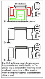
Fig. 15.3 shows a particular case that often arises in valve amps. The circuit in a. shows a simple input stage that uses a shielded cable to screen the grid input from parasitic feedback. However, the circuit has been inadvertently connected to chassis at both ends of the shield,creating a ground loop. Both signal current and ground-loop current flow in the shield as
indicated by the arrows, so the ground loop current will generate a noise voltage across the resistance of the shield that adds directly to the audio voltage, and transformer action in the cable may also couple noise into the
grid wire. To correct this, the loop should be broken by disconnecting one of the chassis connections as in b.
the example that you have posted is for a two wire connection using the core for one half and the outer as the other half.Here's what I had learned...is this situation completely different from shielding an input cable?
From http://www.valvewizard.co.uk/Grounding.pdf
This coaxial cable connection is not a screen around a pair fo signal wires.
The coax outer is the signal wire.
Many forget that a coax is a two wire connection and as a result forget that the outer is a signal wire.
The two wire signal connection must not be broken: it is required to make two connections to the source and to make two connections to the receiver.
Here's what I had learned...is this situation completely different from shielding an input cable?
From http://www.valvewizard.co.uk/Grounding.pdf
1) The good practice is to clamp the cables on the chassis in which case the loop area is insignificant.
2)
so the ground loop current will generate a noise voltage across the resistance of the shield
This is not exact.
I don't know what is a "ground loop current". The voltage across the shield is the same as the one between the same 2 points across the chassis which impedance is less than 50µohm for a copper sheet.
The two wire signal connection must not be broken: it is required to make two connections to the source and to make two connections to the receiver.
I think VictoriaGuy means breaking the connection between shield (outer conductor) and chassis on the amplifier side not breaking the connection between shield (outer conductor) and amplifier input reference.
when the coax outer is being used as a signal wire then you can't connect it to other parts of the system that are not the source signal output and the receiver signal input.
Both parts of the coax must be used as signal wires.
If you have a screened two core cable then the two cores carry the signal and the screen is a true screen. This true screen gets connected to the enclosures at the two ends.
Both parts of the coax must be used as signal wires.
If you have a screened two core cable then the two cores carry the signal and the screen is a true screen. This true screen gets connected to the enclosures at the two ends.
the example that you have posted is for a two wire connection using the core for one half and the outer as the other half.
No, the example from the valve wizard quote is a single conductor (input to grid) with a shield/screen. Unfortunately I couldn't extract the image from his .pdf to post it here, so those interested need to follow the link and scroll down a page or two.
Where both the signal and the 'return' (as some describe it) are involved there would be two conductors with a shield around both.
In either case, I've been told/taught that the shield should only be connected at one end. That's why the 'connect shield at both ends' statement above caught my attention.
It seems to me that this directly contradicts the valve wizard info on grounding (i.e. invites ground loops), so I'll leave y'all to fight it out!If you have a screened two core cable then the two cores carry the signal and the screen is a true screen. This true screen gets connected to the enclosures at the two ends.
🙂
This is not exact.
I don't know what is a "ground loop current". The voltage across the shield is the same as the one between the same 2 points across the chassis which impedance is less than 50µohm for a copper sheet.
If this is correct, then what's wrong with just using many points on the chassis as 'ground' connections, instead of worrying about 'star' and "buss' grounding?
If this is correct, then what's wrong with just using many points on the chassis as 'ground' connections, instead of worrying about 'star' and "buss' grounding?
If you don't use the chassis as power supply reservoir capacitors current return, there is nothing wrong.
look at fig 15.3 again.No, the example from the valve wizard quote is a single conductor (input to grid) with a shield/screen. Unfortunately I couldn't extract the image from his .pdf to post it here, so those interested need to follow the link and scroll down a page or two.
Where both the signal and the 'return' (as some describe it) are involved there would be two conductors with a shield around both.
In either case, I've been told/taught that the shield should only be connected at one end. That's why the 'connect shield at both ends' statement above caught my attention.
It shows three scenarios.
a.) where the builder has not realised the outer is being used as the signal conductor and made two signal to chassis connections.
b.) where the author is showing how one of the two extra chassis connections has been removed to allow the outer to carry signal and not create a chassis loop. But note that the outer carrying the signal return is connected at both ends to the source (input socket) and receiver (amplifier)
c.) shows the two signal conductor inside a screen. The two signal conductors do not carry chassis currents. The screen should be connected at both ends to become an effective screen at high frequencies. If it is connected at one end only the impedance of the length of screen inhibits the flow of interference to enclosure.
If the outer of a coax is carrying signal it does not get connected to the enclosure.
Now go and look at fig 15.14 and fig 15.17
Here he has removed all chassis connections from the signal wiring.
This is the way we build our audio equipment.
The return wire is isolated from the enclosure.
Last edited:
Note:Looking at that figure and the accompanying text, Valve Wizard still says that the shield should only be connected to the chassis at one end, not two, as the post above by Marce recommends.
Very confusing for a beginner!
Very confusing for a beginner!
c.) shows the two signal conductor inside a screen. The two signal conductors do not carry chassis currents. The screen should be connected at both ends to become an effective screen at high frequencies. If it is connected at one end only the impedance of the length of screen inhibits the flow of interference to enclosure.
So ValveWizard Fig 15.3c where the screen is connected at one end only, is incorrect?
If the outer of a coax is carrying signal it does not get connected to the enclosure.
For RF protection, coaxial cable outer conductor must be connected to chassis.
Not on one point with a capacitor (which is not a capacitor at RF) but over the entire connector periphery.
It has become confusing because the Builder does not realise that the outer of the coax is a signal conductor. It is not an exclusive screen/shield.Note:Looking at that figure and the accompanying text, Valve Wizard still says that the shield should only be connected to the chassis at one end, not two, as the post above by Marce recommends.
Very confusing for a beginner!
The signal conductor should NOT be connected to Chassis.
Think about the RCA socket at your input. We all advise that the RCA socket be electrically separate from the enclosure. This advice is ONLY given to comply with the general rule that the Signal conductor should not be connected to the enclosure.
We the Builders have to recognise that a signal connection NEEDS a circuit to make that connection. That circuit NEEDS two wires. This applies to EVERY Signal connection, all are two wire connections. It does not matter that they are a twisted pair or a coaxial or traces across a board. Every inter-module connection requires a Flow and Return and neither of these can be broken.
compare to figures 15.14 and 15.17So ValveWizard Fig 15.3c where the screen is connected at one end only, is incorrect?
There you can see the preferred signal connection. No connection to the enclosure.
You should read the whole document and then review what has been read. If there is some contradictory statement then ask the question.
A coaxial signal connection should not be connected to the enclosure, because the outer is a signal conductor.
A screened two core connection uses the outer as an exclusive screen/shield. This screen/shield should be connected to the enclosure at both ends.
- Status
- Not open for further replies.
- Home
- Design & Build
- Construction Tips
- Beginner question on mounting RCA jack in chassis