Since I went to the trouble to dig up this post I wrote previously on a different forum and since it probably won't be seen in the thread I applied it to, I'll put it here where people that are actually interested in horns will see it, and also expand on the original post a bit.
The common definition for acoustic horn is the simplistic version that follows -
An acoustic horn or waveguide is a tapered sound guide designed to provide an acoustic impedance match between a sound source and free air.
By that definition, the only "true" horns are full size ideal horns, for which the math is clearly defined and can be found all over the internet. Undersized horns don't meet this definition.
First, how do you think this "impedance match", not to mention the huge amounts of in band gain, is realized? It's resonances, all horns have resonances and without resonances you can't have a horn.
Next, let's look at the claimed advantages of horns and how much they apply to full size vs undersized horns, your so called "wonderful virtues of true horns". Hint - undersized horns don't have ANY of the wonderful virtues of true horns.
The claimed advantages are -
- pattern control (dispersion)
- acoustic impedance match between a sound source and free air
- high efficiency through the whole passband
- reactance annulling and lesser pressures on the cone
I'll go through these one by one and show that the undersized front loaded horns don't have any of these characteristics, only full size front loaded horns do.
And then at the end, I'll show how similar ported boxes are to front loaded horns. Ported boxes have a lot of resonances are operate very similarly to front loaded horns in this respect, although most of the ported box resonances are usually high above the passband and are usually ignored - but that doesn't mean they are not there.
To illustrate what's really going on let's examine a couple of different horns. They are both very large, but one is small compared to the low knee frequency and one is the ideal size (which means it's huge). Both these horns use the same driver but the horns are very different. The small one is still very large at almost 750 liters and with a mouth size of 6550 sq cm but it is still massively undersized compared to it's low knee frequency wavelength. The large one is ideally suited to it's low knee frequency, having a mouth size of over 50000 sq cm and a volume of almost 5000 liters.
Dispersion patterns are a function of size and frequency wave length. If there is a horn or waveguide involved the shape of the flare also has something to do with dispersion.
With tweeters the wavelengths are small because the frequencies are high so it doesn't take a large guide to control their dispersion pattern. With bass horns the wavelengths are large. Does that mean they can't be controlled? Absolutely not.
A small bass horn, the kind you are likely to see being built by a diy'er is much too small to control dispersion at subwoofer frequencies. But a large horn can have a great deal of pattern control.
Let's look at the dispersion patterns of the two example horns. The small one is on the left, the large horn is on the right. The top row is dispersion at 35 hz (near the bottom of the passband), the bottom row is dispersion at 100 hz (top of the passband).
So clearly the small horn is too small to have much effect on directivity even at the top of the passband. The large horn has a small amount of influence over directivity even at the bottom of the passband, and a huge impact at the top of the passband. What goes for tweeters goes for subwoofers too, the difference is frequency vs size, and undersized horns can't control dispersion.
The "impedance transformer" (cone to air) is one of those old sayings that gets passed on all the time but it's not really true at all for small horns. Let's look at the impedance curve of the two example horns. Small on left, large on right.
The small horn has an impedance curve that looks a lot like a transmission line, which we know is not considered an impedance transformer. The large horn's impedance curve is much different. The spikes are damped, the dips are not as deep and the average level in the passband is higher.
In the small horn there are narrow bands of very high efficiency corresponding to the huge impedance spikes and in between the spikes the efficiency is very low. The large horn has a higher level of efficiency across the entire passband due to it's sheer size and a much more calm impedance curve. This is what they mean by impedance matching and it doesn't apply to small horns. The impedance curve is where you see it but that's not really what they are talking about either. What they mean is that the impedance curve, the frequency response and everything else is smooth, not spiky so the cone is able to "see" a more constant radiation resistance in the air load at all frequencies in the passband.
Here's actual efficiency. Small horn on left, large on right, 120 liter ported box tuned to about 32 hz on bottom. The small horn does have a lot more efficiency than the much smaller ported box at most frequencies, that's to be expected based on size and having so many impedance peaks inside the passband. The large horn efficiency is much higher than both.
Clearly efficiency spikes at the same frequencies the impedance peaks are at. So if you line up a bunch of impedance peaks inside the passband you can have boosted efficiency for as much as a 3 octave passband. And the larger the enclosure, the more acoustic gain, the more efficiency.
Some people might not be aware of what the ported box is actually doing. The front wave is out of phase with the back across a lot of the passband so they are actually fighting each other. At some frequencies the direct radiator output wins and at others the box resonances win. It's a complex summation. This is the direct radiator output (left), the port output (right) and the summed response (bottom).
For people that only use WinISD or similar helmholtz type simulators it may not be clear that ported boxes have a series of resonances like a horn. But when you look at port output alone in a picture like that directly above it becomes clear that ported boxes have ALL KINDS of resonances. The people who are aware that there are ported box resonances usually just ignore them, thinking they will be too far above the passband to matter.
But when you look at the port output image it becomes clear that ported boxes and horns are not really all that different. The horn actively uses it's shape to line all those resonances up into a pretty row and give them the individual acoustic gain that they need to provide a propped up flat(ish) response over as much as 3 octaves. The ported box has the same type of resonances but they are at erratic frequencies where they can't help but can only cause trouble. Therefore the resonances need to be pushed up way out of the passband or stuffing must be applied to calm them down. MLTL and the various different types of TL are ported box variants that attempt to make use of ported box resonances instead of ignoring them or stuffing the life out of them. Some types of TL are remarkably similar to undersized horns.
The resonant enclosure types are not that different, they all lie on a continuum based on shape and layout. They all have a series of resonances. How they deal with these resonances might be different but they all have them.
And since that post hinted at but didn't include a picture of frequency response or excursion characteristics of a full size vs undersized horn, here's a random example showing the much flatter frequency response and excursion curve of a full size horn.
Full size on top, undersized on bottom. Both shown with equal input voltage.
The full size horn is about 4500 liters, the small horn is about 370 liters.
Both horns have approximately 2:1 compression ratio.
Let's go a step further and look at cone pressure and reactance annulling. These are the same horns shown in the last pic, shown with the same (equal) voltage applied.
Top row is the undersized horn, bottom row is the full size horn.
Left column is pressure on the horn side, right column is pressure on the sealed rear chamber side.
Notice two things in that image - first the smaller horn has much higher pressure on the horn side than the much larger full size horn all across the entire bandwidth. (The first big spike in pressure won't matter so much if the horn is high passed, but the higher pressure through the rest of the passband will still apply.)
Second, the pressures on both sides of the full size horn are fairly well balanced (peaking at similar values of pressure) whereas the pressures on either side of the undersized horn cone are at dramatically different pressure. We'll see what this means in the next image.
This is total pressure on the cone - the actual normalized pressure the cone experiences when considering pressure from both sides (not just either side separately as shown above).
Notice the same two things in this picture. First, the large full size horn experiences dramatically less cone pressure and stress across the entire bandwidth despite putting out dramatically higher spl.
Second, notice that the pressure peaks are fairly well balanced (peaking at the similar pressures) across the whole passband, and even below the passband. On the other hand, the undersized horn has very little pressure at frequencies below tuning and very high pressures at the peaks above tuning.
This is reactance annulling at work in the large horn and not so much in the small horn. When the pressure peaks below and above tuning are balanced you have good reactance annulling.
Note that the pressure peaks above and below tuning are not exactly the same in the full size horn but they are close. They could have been closer if this was an ideal horn for this driver, but an ideal horn for this driver would have an insanely high compression ratio so compromises must be made resulting in less than perfect reactance annulling.
The common definition for acoustic horn is the simplistic version that follows -
An acoustic horn or waveguide is a tapered sound guide designed to provide an acoustic impedance match between a sound source and free air.
By that definition, the only "true" horns are full size ideal horns, for which the math is clearly defined and can be found all over the internet. Undersized horns don't meet this definition.
First, how do you think this "impedance match", not to mention the huge amounts of in band gain, is realized? It's resonances, all horns have resonances and without resonances you can't have a horn.
Next, let's look at the claimed advantages of horns and how much they apply to full size vs undersized horns, your so called "wonderful virtues of true horns". Hint - undersized horns don't have ANY of the wonderful virtues of true horns.
The claimed advantages are -
- pattern control (dispersion)
- acoustic impedance match between a sound source and free air
- high efficiency through the whole passband
- reactance annulling and lesser pressures on the cone
I'll go through these one by one and show that the undersized front loaded horns don't have any of these characteristics, only full size front loaded horns do.
And then at the end, I'll show how similar ported boxes are to front loaded horns. Ported boxes have a lot of resonances are operate very similarly to front loaded horns in this respect, although most of the ported box resonances are usually high above the passband and are usually ignored - but that doesn't mean they are not there.
To illustrate what's really going on let's examine a couple of different horns. They are both very large, but one is small compared to the low knee frequency and one is the ideal size (which means it's huge). Both these horns use the same driver but the horns are very different. The small one is still very large at almost 750 liters and with a mouth size of 6550 sq cm but it is still massively undersized compared to it's low knee frequency wavelength. The large one is ideally suited to it's low knee frequency, having a mouth size of over 50000 sq cm and a volume of almost 5000 liters.
An externally hosted image should be here but it was not working when we last tested it.
Dispersion patterns are a function of size and frequency wave length. If there is a horn or waveguide involved the shape of the flare also has something to do with dispersion.
With tweeters the wavelengths are small because the frequencies are high so it doesn't take a large guide to control their dispersion pattern. With bass horns the wavelengths are large. Does that mean they can't be controlled? Absolutely not.
A small bass horn, the kind you are likely to see being built by a diy'er is much too small to control dispersion at subwoofer frequencies. But a large horn can have a great deal of pattern control.
Let's look at the dispersion patterns of the two example horns. The small one is on the left, the large horn is on the right. The top row is dispersion at 35 hz (near the bottom of the passband), the bottom row is dispersion at 100 hz (top of the passband).
An externally hosted image should be here but it was not working when we last tested it.
So clearly the small horn is too small to have much effect on directivity even at the top of the passband. The large horn has a small amount of influence over directivity even at the bottom of the passband, and a huge impact at the top of the passband. What goes for tweeters goes for subwoofers too, the difference is frequency vs size, and undersized horns can't control dispersion.
The "impedance transformer" (cone to air) is one of those old sayings that gets passed on all the time but it's not really true at all for small horns. Let's look at the impedance curve of the two example horns. Small on left, large on right.
An externally hosted image should be here but it was not working when we last tested it.
The small horn has an impedance curve that looks a lot like a transmission line, which we know is not considered an impedance transformer. The large horn's impedance curve is much different. The spikes are damped, the dips are not as deep and the average level in the passband is higher.
In the small horn there are narrow bands of very high efficiency corresponding to the huge impedance spikes and in between the spikes the efficiency is very low. The large horn has a higher level of efficiency across the entire passband due to it's sheer size and a much more calm impedance curve. This is what they mean by impedance matching and it doesn't apply to small horns. The impedance curve is where you see it but that's not really what they are talking about either. What they mean is that the impedance curve, the frequency response and everything else is smooth, not spiky so the cone is able to "see" a more constant radiation resistance in the air load at all frequencies in the passband.
Here's actual efficiency. Small horn on left, large on right, 120 liter ported box tuned to about 32 hz on bottom. The small horn does have a lot more efficiency than the much smaller ported box at most frequencies, that's to be expected based on size and having so many impedance peaks inside the passband. The large horn efficiency is much higher than both.
Clearly efficiency spikes at the same frequencies the impedance peaks are at. So if you line up a bunch of impedance peaks inside the passband you can have boosted efficiency for as much as a 3 octave passband. And the larger the enclosure, the more acoustic gain, the more efficiency.
An externally hosted image should be here but it was not working when we last tested it.
Some people might not be aware of what the ported box is actually doing. The front wave is out of phase with the back across a lot of the passband so they are actually fighting each other. At some frequencies the direct radiator output wins and at others the box resonances win. It's a complex summation. This is the direct radiator output (left), the port output (right) and the summed response (bottom).
An externally hosted image should be here but it was not working when we last tested it.
For people that only use WinISD or similar helmholtz type simulators it may not be clear that ported boxes have a series of resonances like a horn. But when you look at port output alone in a picture like that directly above it becomes clear that ported boxes have ALL KINDS of resonances. The people who are aware that there are ported box resonances usually just ignore them, thinking they will be too far above the passband to matter.
But when you look at the port output image it becomes clear that ported boxes and horns are not really all that different. The horn actively uses it's shape to line all those resonances up into a pretty row and give them the individual acoustic gain that they need to provide a propped up flat(ish) response over as much as 3 octaves. The ported box has the same type of resonances but they are at erratic frequencies where they can't help but can only cause trouble. Therefore the resonances need to be pushed up way out of the passband or stuffing must be applied to calm them down. MLTL and the various different types of TL are ported box variants that attempt to make use of ported box resonances instead of ignoring them or stuffing the life out of them. Some types of TL are remarkably similar to undersized horns.
The resonant enclosure types are not that different, they all lie on a continuum based on shape and layout. They all have a series of resonances. How they deal with these resonances might be different but they all have them.
And since that post hinted at but didn't include a picture of frequency response or excursion characteristics of a full size vs undersized horn, here's a random example showing the much flatter frequency response and excursion curve of a full size horn.
Full size on top, undersized on bottom. Both shown with equal input voltage.
The full size horn is about 4500 liters, the small horn is about 370 liters.
Both horns have approximately 2:1 compression ratio.
An externally hosted image should be here but it was not working when we last tested it.
Let's go a step further and look at cone pressure and reactance annulling. These are the same horns shown in the last pic, shown with the same (equal) voltage applied.
Top row is the undersized horn, bottom row is the full size horn.
Left column is pressure on the horn side, right column is pressure on the sealed rear chamber side.
An externally hosted image should be here but it was not working when we last tested it.
Notice two things in that image - first the smaller horn has much higher pressure on the horn side than the much larger full size horn all across the entire bandwidth. (The first big spike in pressure won't matter so much if the horn is high passed, but the higher pressure through the rest of the passband will still apply.)
Second, the pressures on both sides of the full size horn are fairly well balanced (peaking at similar values of pressure) whereas the pressures on either side of the undersized horn cone are at dramatically different pressure. We'll see what this means in the next image.
This is total pressure on the cone - the actual normalized pressure the cone experiences when considering pressure from both sides (not just either side separately as shown above).
An externally hosted image should be here but it was not working when we last tested it.
Notice the same two things in this picture. First, the large full size horn experiences dramatically less cone pressure and stress across the entire bandwidth despite putting out dramatically higher spl.
Second, notice that the pressure peaks are fairly well balanced (peaking at the similar pressures) across the whole passband, and even below the passband. On the other hand, the undersized horn has very little pressure at frequencies below tuning and very high pressures at the peaks above tuning.
This is reactance annulling at work in the large horn and not so much in the small horn. When the pressure peaks below and above tuning are balanced you have good reactance annulling.
Note that the pressure peaks above and below tuning are not exactly the same in the full size horn but they are close. They could have been closer if this was an ideal horn for this driver, but an ideal horn for this driver would have an insanely high compression ratio so compromises must be made resulting in less than perfect reactance annulling.
Last edited:
In summary, all of the characteristics commonly attributed to horns are seen in full size horns but NONE of them are seen in undersized horns.
The claimed advantages are -
- pattern control (dispersion)
- acoustic impedance match between a sound source and free air
- high efficiency through the whole passband
- reactance annulling and lesser pressures on the cone
Also, ported boxes are not that different than horns from a resonant device perspective. The main differences are size and shape which affect the spacing and amplitude of the resonances.
(The sealed chamber in the front loaded horn does change things but that's not pertinent to this discussion so far, I can go over the differences in devices with a sealed chamber (flh) and without (ported box, tl, tapped horn) if there's interest in that.
Good stuff. So basically we're all just design 1/4 wave resonators rather than true horns...
BTW, another way of reducing port resonances in a vented alignment is to simply use a smaller, shorter vent. Of course, this does introduce some other issues, if the alignment in question is for a subwoofer...
BTW, another way of reducing port resonances in a vented alignment is to simply use a smaller, shorter vent. Of course, this does introduce some other issues, if the alignment in question is for a subwoofer...
just a guy
The sealed chamber in the front loaded horn does change things but that's not pertinent to this discussion so far,
I think that showing, what a difference porting the back chamber can make, would be useful.
I can go over the differences in devices with a sealed chamber (flh) and without (ported box, tl, tapped horn) if there's interest in that.
It ALL interests me
") & i'm sure others too, even if they don't post !
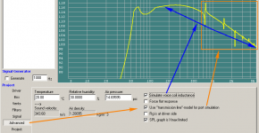
& i'm sure others too, even if they don't post !Actually, WinISD can show resonances in v0.7.0.900 under the Advanced Tab. Also the effect of inductance can be included.
Brian Steele
Good stuff. So basically we're all just design 1/4 wave resonators rather than true horns...
Maybe HR should be renamed QWR from now on then
.BTW, another way of reducing port resonances in a vented alignment is to simply use a smaller, shorter vent. Of course, this does introduce some other issues, if the alignment in question is for a subwoofer..
Yes indeed. See my above screenie for a visual sim
Attachments
Good stuff. So basically we're all just design 1/4 wave resonators rather than true horns...
There are some true diy horns but not many. For example, a full stack of 6 - 8 Labhorns was designed to be a modular full size horn.
But the "little" horns we usually make (both diy and commercial) are not really true horns by the usual definition of "acoustical impedance transformer", no.
Horns were defined mathematically decades before the average person could quantify their behavior (before simulators were invented and before the average person could measure response) so when people almost immediately started making horns smaller then the math indicated they should be, they still used the definition to define these small horns, and it simply doesn't apply.
Sure you get some extra gain from these small horns, and some behavior at the top of the passband that's somewhat hornlike but if you compare the impedance curve, frequency response curve, efficiency curve, displacement curve, you see that a full size true horn is dramatically smoother than even the top of the passband of a truncated horn.
It's this smooth (non peaky) behavior in all these different graphs that show the true nature of the impedance transformer.
I think that showing, what a difference porting the back chamber can make, would be useful.
Personally I don't find porting a horn chamber to be that useful. My alternative solution would be to design a flh with a lower f3 or use a tapped horn instead. So I won't be showing examples of ported horn chambers.
It ALL interests me
In this case, maybe tomorrow I can show the differences between flh vs tapped and ported - specifically the difference the flh sealed chamber makes. Maybe not tomorrow though - I have to get my dog put down so I'm not sure what kind of day it's going to be.
Actually, WinISD can show resonances in v0.7.0.900 under the Advanced Tab. Also the effect of inductance can be included.
True, but most people ignore that feature and I wouldn't trust it without doing a comparison with reputable 1/4 wave software like Hornresp first. I'm pretty sure you would find that it's just simulating the port resonances, not the enclosure resonances. And even then it might not be simulating the port resonances in an accurate fashion.
As far as inductance, that shouldn't be a checkbox feature, all sims should be showing inductance effects. And of course this is just basic inductance effects, not lossy inductance effects using the complex inductance parameters like Unibox can simulate.
Maybe HR should be renamed QWR from now on then
No, Hornresp was made to simulate horns. With Leach's math incorporated you could argue that it's main function is to simulate full size horns. The fact that it can simulate a whole bunch of other stuff is a huge benefit, but I think Hornresp's name is fitting.
.Originally Posted by just a guy
So I won't be showing examples of ported horn chambers
Well that's a pity, as it can be a Very useful addition, if done properly
Looking forward to your further posts. I was only joking about renaming HR to QWR, i just forgot to add a smily
I'm Very sorry to hear about your dog, & having pets myself for many years, i know the distress things like can cause.
Excellent writeup! I am not sure if this stuff is finally sinking in or how you explained things (probably), but this really clicks for me. This is definitely WIKI/sticky material. This forum desperately needs more of this. I look forward to future installments.
My condolences to you on this day.
My condolences to you on this day.
Yes! Absolutely great detailed and comprehensive information, JAG.
I agree that it should be a thread that makes it into some sort of readily accessible sticky/wiki, and not get lost in the shuffle like others do...
For myself (unfortunately), this gets filed under "gonna need a bigger house".
*edit* Well, not entirely, I still may do a IB in the basement HT..
Again, great write-up..
Last edited:
Ok, moving on, let's look at the differences between designs with a sealed chamber (like flh) vs designs without (ported box, tl, tapped horn, etc). For this example we'll look at a flh vs a tapped horn, but be aware that ported boxes and transmission lines will act very similarly to tapped horns in the characteristics we are going to look at here, so we don't have to look at examples of every single different type of enclosure.
For this example I've chosen to design a flh and a tapped horn with the same internal volume, 450 liters each. And I've chosen to design them both to have a very similar low knee frequency. Both designs use the same driver and both are close enough to a 2:1 compression ratio.
The tapped horn is a simple single fold with PAR segments and the flh is a simple single segment 0.5 T hypex flare. Here are the inputs and schematic of both designs.
Next is a picture of their respective frequency response, excursion (both shown with 1 watt input), impedance and phase.
The big things to notice here are that -
- with an equal input power both designs provide approximately the same spl. This is because acoustic gain is a function of enclosure size
- the tapped horn uses a lot more excursion than the flh when given equal amounts of power
- the two designs have a dramatically different tuning frequency despite having the same low knee frequency, you can see this by the first big notch in excursion happening at different frequencies
- the impedance curve is also dramatically different despite having roughly the same low knee frequency
- the tapped horn tuning is at a frequency in between the lowest two impedance peaks, and this tuning frequency is also roughly the same frequency that the low knee occurs at - the flh tuning is also at a frequency in between the lowest two impedance peaks but in contrast to the tapped horn the low knee frequency is roughly the same frequency as the lowest impedance peak; the low knee happens at a different (lower) frequency than the tuning frequency
- phase is pretty similar for both these designs through most of the passband but starts to diverge at the top of the passband; this is because frequency response is pretty similar though most of the passband but starts to diverge at the top of the passband
Now let's look at a third image. This time we are adding high pass filters to both designs and increasing power so that they both peak at 10 mm excursion. All graphs in this image have the high pass filter and full power to reach excursion limits applied.
The fact that they have a vastly different tuning and excursion behavior despite having the same low knee frequency means that they need vastly different high pass filters.
The tapped horn needs a high pass filter at 24 hz, 4th order BW.
The flh needs a high pass filter at 34 hz, 4th order BW.
The resulting high pass filters affect the response very differently. Because the tapped horn's high pass filter is outside the passband it has very little effect inside the passband.
But because the flh's high pass filter is INSIDE the passband (above the low knee frequency) it has a pretty dramatic effect, it eats up a few db at the low knee, changing the response curve shape very visibly.
By looking at the top row of graphs you can see that both designs are capable of roughly the same spl at the low knee and that the flh has a huge advantage at higher frequencies.
But when looking the the second row of graphs, driver power, it becomes clear that the front loaded horn needs to consume over 2x more power to reach it's excursion limits. This can lead to differences not seen in the sims due to the flh suffering far more from thermal compression. (Tapped horn driver power is on the left, flh is on the right.)
So if flat response down to the low knee and low risk of thermal issues is a high priority the tapped horn shown here might be a better choice. If very high spl at higher frequencies is a priority and power compression is not a big concern then the flh might be a better choice.
The last row of graphs shows the efficiency of each design. As expected, the tapped horn has higher efficiency at the low knee and the flh has more efficiency at higher frequencies in the passband. This is pretty clear just by looking at the previous graphs.
Of particular interest here is that the flh efficiency spike at the low knee is actually happening at 28 hz which is BELOW the low knee, at a frequency well below the high pass filter, so a lot of that efficiency is just filtered out. The tapped horn doesn't have this problem at all.
So that's a quick look at how a sealed chamber affects things vs designs without a sealed chamber. For a given size and power input, both designs give a similar frequency response and spl. But since the designs have very different tuning and excursion despite having the same low knee frequency, they require different high pass filters and different amounts of power to reach excursion limits, and that changes things a lot.
It might also be useful to take a look at using flhs without a high pass filter, in that case they can come close to tapped horn performance at the low knee with a similar amount of power because in that case you don't have a high pass filter eating 3 - 6 db out of your low knee. But you need high excursion drivers to make that work. In any case, the flh sealed chamber and excursion reduction allows for the possibility of running without a low knee strangling high pass filter.
For this example I've chosen to design a flh and a tapped horn with the same internal volume, 450 liters each. And I've chosen to design them both to have a very similar low knee frequency. Both designs use the same driver and both are close enough to a 2:1 compression ratio.
The tapped horn is a simple single fold with PAR segments and the flh is a simple single segment 0.5 T hypex flare. Here are the inputs and schematic of both designs.
An externally hosted image should be here but it was not working when we last tested it.
Next is a picture of their respective frequency response, excursion (both shown with 1 watt input), impedance and phase.
The big things to notice here are that -
- with an equal input power both designs provide approximately the same spl. This is because acoustic gain is a function of enclosure size
- the tapped horn uses a lot more excursion than the flh when given equal amounts of power
- the two designs have a dramatically different tuning frequency despite having the same low knee frequency, you can see this by the first big notch in excursion happening at different frequencies
- the impedance curve is also dramatically different despite having roughly the same low knee frequency
- the tapped horn tuning is at a frequency in between the lowest two impedance peaks, and this tuning frequency is also roughly the same frequency that the low knee occurs at - the flh tuning is also at a frequency in between the lowest two impedance peaks but in contrast to the tapped horn the low knee frequency is roughly the same frequency as the lowest impedance peak; the low knee happens at a different (lower) frequency than the tuning frequency
- phase is pretty similar for both these designs through most of the passband but starts to diverge at the top of the passband; this is because frequency response is pretty similar though most of the passband but starts to diverge at the top of the passband
An externally hosted image should be here but it was not working when we last tested it.
Now let's look at a third image. This time we are adding high pass filters to both designs and increasing power so that they both peak at 10 mm excursion. All graphs in this image have the high pass filter and full power to reach excursion limits applied.
The fact that they have a vastly different tuning and excursion behavior despite having the same low knee frequency means that they need vastly different high pass filters.
The tapped horn needs a high pass filter at 24 hz, 4th order BW.
The flh needs a high pass filter at 34 hz, 4th order BW.
The resulting high pass filters affect the response very differently. Because the tapped horn's high pass filter is outside the passband it has very little effect inside the passband.
But because the flh's high pass filter is INSIDE the passband (above the low knee frequency) it has a pretty dramatic effect, it eats up a few db at the low knee, changing the response curve shape very visibly.
By looking at the top row of graphs you can see that both designs are capable of roughly the same spl at the low knee and that the flh has a huge advantage at higher frequencies.
But when looking the the second row of graphs, driver power, it becomes clear that the front loaded horn needs to consume over 2x more power to reach it's excursion limits. This can lead to differences not seen in the sims due to the flh suffering far more from thermal compression. (Tapped horn driver power is on the left, flh is on the right.)
So if flat response down to the low knee and low risk of thermal issues is a high priority the tapped horn shown here might be a better choice. If very high spl at higher frequencies is a priority and power compression is not a big concern then the flh might be a better choice.
The last row of graphs shows the efficiency of each design. As expected, the tapped horn has higher efficiency at the low knee and the flh has more efficiency at higher frequencies in the passband. This is pretty clear just by looking at the previous graphs.
Of particular interest here is that the flh efficiency spike at the low knee is actually happening at 28 hz which is BELOW the low knee, at a frequency well below the high pass filter, so a lot of that efficiency is just filtered out. The tapped horn doesn't have this problem at all.
An externally hosted image should be here but it was not working when we last tested it.
So that's a quick look at how a sealed chamber affects things vs designs without a sealed chamber. For a given size and power input, both designs give a similar frequency response and spl. But since the designs have very different tuning and excursion despite having the same low knee frequency, they require different high pass filters and different amounts of power to reach excursion limits, and that changes things a lot.
It might also be useful to take a look at using flhs without a high pass filter, in that case they can come close to tapped horn performance at the low knee with a similar amount of power because in that case you don't have a high pass filter eating 3 - 6 db out of your low knee. But you need high excursion drivers to make that work. In any case, the flh sealed chamber and excursion reduction allows for the possibility of running without a low knee strangling high pass filter.
Last edited:
Just to round this out (and because it only takes a minute to show) here's the tapped horn at xmax with a high pass filter vs the flh at xmax without a high pass filter.
As you can see it is viable to run the flh without a high pass but it requires a driver with a lot of excursion potential, otherwise the tapped horn is the better choice. It does not require high power handling though, as you run through excursion pretty quickly without the high pass on the flh.
Driver power shows tapped on left, flh on right, this shows clearly that it doesn't take much power for the flh to reach it's excursion limits without a high pass.
An externally hosted image should be here but it was not working when we last tested it.
As you can see it is viable to run the flh without a high pass but it requires a driver with a lot of excursion potential, otherwise the tapped horn is the better choice. It does not require high power handling though, as you run through excursion pretty quickly without the high pass on the flh.
Driver power shows tapped on left, flh on right, this shows clearly that it doesn't take much power for the flh to reach it's excursion limits without a high pass.
Ok, here's group delay.
Top row without high pass filters.
Bottom row with high pass filters (24 hz 4th order BW for the tapped, 34 hz 4th order BW for the flh)
Left column - tapped horn
Right column - flh
Top row without high pass filters.
Bottom row with high pass filters (24 hz 4th order BW for the tapped, 34 hz 4th order BW for the flh)
Left column - tapped horn
Right column - flh
An externally hosted image should be here but it was not working when we last tested it.
About first post:
I could stick you some mistakes, but they are all meaningless due to wrong look at the very beginning.
The definition doesnt say what bandwidth it should match the impedance.
The whole "small" horn is wrong made. Its all calculated characteristics are wrong. Noone would like to play on horn sounding like this.
Here is some similar volume horn. Technically accurate.
Naturally the impedance curve now is more similar to your 5000dm3 horn. Rest parameters look also more like big horn.
The same mistake with tapped horns. You didnt simulate tapped horns. You simulated some bad transmission lines.
Reassuming, you can make small horn that match totally your definition and its not in drastic cost of driver repairs, but in cost of bandtwitch widtch(not characteristics) and time spent on the design. Its harder to make small horns.
Smaller hybrides are more effective then larger ones. Its small difference 0,5db.
I could stick you some mistakes, but they are all meaningless due to wrong look at the very beginning.
The common definition for acoustic horn is the simplistic version that follows -
An acoustic horn or waveguide is a tapered sound guide designed to provide an acoustic impedance match between a sound source and free air.
By that definition, the only "true" horns are full size ideal horns, for which the math is clearly defined and can be found all over the internet. Undersized horns don't meet this definition.
The definition doesnt say what bandwidth it should match the impedance.
The whole "small" horn is wrong made. Its all calculated characteristics are wrong. Noone would like to play on horn sounding like this.
Here is some similar volume horn. Technically accurate.
An externally hosted image should be here but it was not working when we last tested it.
An externally hosted image should be here but it was not working when we last tested it.
An externally hosted image should be here but it was not working when we last tested it.
An externally hosted image should be here but it was not working when we last tested it.
An externally hosted image should be here but it was not working when we last tested it.
Naturally the impedance curve now is more similar to your 5000dm3 horn. Rest parameters look also more like big horn.
The same mistake with tapped horns. You didnt simulate tapped horns. You simulated some bad transmission lines.
Reassuming, you can make small horn that match totally your definition and its not in drastic cost of driver repairs, but in cost of bandtwitch widtch(not characteristics) and time spent on the design. Its harder to make small horns.
Smaller hybrides are more effective then larger ones. Its small difference 0,5db.
Last edited:
About first post:
I could stick you some mistakes, but they are all meaningless due to wrong look at the very beginning.
If you think I've made a mistake go ahead and point it out. I'm about to show you a bunch of mistakes and misconceptions that you just posted.
The definition doesnt say what bandwidth it should match the impedance.
I think it implies heavily that the impedance matching should be across the entire usable passband, any less (or anywhere outside the passband) would be pretty useless.
The whole "small" horn is wrong made. Its all calculated characteristics are wrong. Noone would like to play on horn sounding like this.
There's no such thing as "wrong", only better or worse when compared to a specific set of goals. I made no attempt to optimize ANY of the designs I've shown in this discussion, they are all random 10 second designs.
So let's look at the design compared to yours. The original pics from post 1 were created about a year ago, I don't know what driver was used and I didn't capture the inputs so I don't know the horn details either. The only frequency response I showed in post 1 was from a newer design I created on that day. Here it is compared to yours.
An externally hosted image should be here but it was not working when we last tested it.
The first problem I see with comparing these two (even though I didn't save any of the horn or driver data for my example) is that mine can be folded into an efficient square or rectangular enclosure, yours can't. Looking at your inputs, you've used a pure EXP segment for the bulk of your horn flare. That type of pure EXP segment flares out way too fast at the mouth which is going to make it nearly impossible to fold your design up in an efficient way.
The next problem is that my example is 370 liters with a low knee around 36 hz while your design is 599 liters with a low knee around 50 hz. This is about as unfair as you could possibly get, yours is almost twice as large and tuned 1/2 octave higher.
I know you are talking about this small 370 liter horn when you say "The whole "small" horn is wrong made. Its all calculated characteristics are wrong. Noone would like to play on horn sounding like this. because this is the only frequency response shown in post 1.
So congrats, you've shown a design with smoother and flatter frequency response and all you needed to do to achieve that was make it almost 2x bigger, tune it 1/2 octave higher and use a horn flare that can't be efficiently folded into a box.
Reassuming, you can make small horn that match totally your definition and its not in drastic cost of driver repairs, but in cost of bandtwitch widtch(not characteristics) and time spent on the design. Its harder to make small horns.
Ok, let's investigate this claim that small horns can match the definitions of a full size horn. Let's recap the definitions first.
The claimed advantages are -
- pattern control (dispersion)
- acoustic impedance match between a sound source and free air
- high efficiency through the whole passband
- reactance annulling and lesser pressures on the cone
Now the first thing to do (and you can bet I'm going to document everything this time since I'm being challenged) is create a full size horn to compare to your 599 liter small horn design. We'll use the same driver, same input power, same low knee frequency and let Hornresp design the full size horn. The horn loaded bandwidth is going to be limited to 45 - 150 hz due to the compression ratio and rear chamber size issues.
An externally hosted image should be here but it was not working when we last tested it.
Now the first thing to notice is that a full size horn for the driver and low knee that you have chosen is only 1475 liters. That's only 2.5x larger than your "small" horn. When the difference between the "small" horn and the full size horn is so small it's no wonder that the differences in response characteristics are also small.
Compare this 2.5:1 size ratio to the two different examples I showed in post 1.
First example - small horn 744 liters, full size horn 4874 liters, ratio 6.6:1
Second example - small horn 370 liter, full size horn 4500 liters, ratio 12.2:1
So while I was busy comparing MASSIVELY undersized horns to full size horns, you used an example "small" horn that was only 2.5x smaller than a full size horn for your chosen bandwidth which is only a moderate size difference in comparison to my examples. I'm not sure whether to characterize this as an oversight, misdirection or outright cheating on your part. Either way your example is not even remotely similar to any of mine, your example is simply not that undersized.
Ok, moving on let's examine each of the full size horn characteristics and see how yours stacks up.
1. pattern control (dispersion)
I don't even know why I'm bothering, as your example is way too small to exhibit any significant pattern control even at the top of the passband, but let's go through the motions anyway. (Note - I had to make your "small" horn have a single EXP segment to run the directivity sim, it made no significant difference to the horn itself.)
An externally hosted image should be here but it was not working when we last tested it.
Small horn on left, full size horn on right, both shown at 100 hz. The full size horn has significantly more pattern control despite the fact that it's only 2.5x larger than the "small" horn. This is as expected.
Verdict - small horn fails at pattern control.
2. Efficiency across the entire passband.
An externally hosted image should be here but it was not working when we last tested it.
Your "small" horn has decent efficiency (which is not surprising because it's pretty big for the bandwidth it covers) but it's only about 12 percent at lower frequencies and doesn't really register as "high" efficiency until it gets close to the top of a subwoofer's usable bandwidth. Contrarily, the full size horn has high and UNIFORM efficiency across the ENTIRE bandwidth.
Verdict - small horn fails at efficiency.
3. acoustic impedance match between a sound source and free air
As I said, you can see the "impedance matching" between the horn and air in all the graphs, just look for smoother and more uniform response in all graphs. We've already seen the efficiency graph, now let's look at the frequency response, impedance and excursion graphs. In all cases small horn on left, full size on right.
An externally hosted image should be here but it was not working when we last tested it.
ALL the full size graphs are smoother, flatter and more uniform. Also note that in the impedance graph the "small" horn has a minimum of 6 ohms in the passband while the full size impedance minimum is 8 ohms.
The full size horn raised the impedance across the entire bandwidth by a significant amount. This is a big deal, meaning that the full size horn is actually drawing a lot less power even though the voltage input is exactly the same in both examples. This equates to a lot less thermal issues for the larger horn.
Verdict - small horn fails at impedance matching the horn to the air load.
4. reactance annulling and lesser pressures on the cone
An externally hosted image should be here but it was not working when we last tested it.
Small horn left, full size right. Nevermind the area below tuning, this will be wiped out by the required high pass filter in both cases anyway. Above tuning the small horn peaks at 6500 Pa and the full size horn is down around 5000 Pa.
This is a pretty dramatic difference even though the full size horn is only 2.5x larger.
Verdict - small horn fails at reducing pressures on the cone.
Last edited:
- Status
- This old topic is closed. If you want to reopen this topic, contact a moderator using the "Report Post" button.
- Home
- Loudspeakers
- Subwoofers
- Characteristic of full size vs undersized horns vs ported boxes