Amplifier this filter works with voltages less than 2 volts. This amplifier assembled from 2 opamp, they are covered by overall NFB (we call it "composite"). Therefore, this amplifier has low distortion.What sort of spec does this type of filter need? Does it need 1ppzillion THD too?
You can go to this forum: Audio Perfection Forum and ask the person Audio Perfection Forum. He is the author of this filter and he lives in the United States.
I don't think the level of distortion for 1 kHz is a good indicator of the quality of the amplifier. Therefore, I did not measure distortion for this frequency - for the past 15 years.Do you have separate ones for 1kHz and 20kHz?
PS: And I have even less brains than you. 🙂
Last edited:
I use the calculation TKHD 20K during the simulation of the amp models for quick evaluation of changes of the circuit. Because sound cards have a narrow band of frequencies, while measurement method is used with CCIF IM 19+20kHz.It is important to recognize that THD-20 is a metric for high-frequency nonlinearity, and whether one thinks that one can hear the harmonics is not relevant. I personally believe that what one hears is the IM products that result from high frequency nonlinearity. For example, I do like CCIF IM with 19+20kHz. That having been said, it does not invalidate THD-20 as a good measure of HF nonlinearity. It is very important, however, to realize that the relative amplitudes of the intermodulation products will usually be smaller, and often not numerically comparable to, the THD-20 percentages.
IMHO you can't use IMD figures to calculate THD20k and vice versa.
http://www.diyaudio.com/forums/soli...s-ab-power-amp-200w8r-400w4r.html#post3945064
In the above example the measured THD 20k was about 0.001% @100W8R while the measured IMD was about 0.0005% @ 100W8R.
I and many others would really like to know how you (T117) measure such low THD values (sub ppm) with a simple sound card...
BR, Toni
I and many others would really like to know how you (T117) measure such low THD values (sub ppm) with a simple sound card...
BR, Toni
I think his answers imply he didn't.
Jan
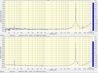
For example, here are a couple of graphs, made using a filter with a suppression of 20 kHz by 20 dB.
All I can see is that your filter suppresses the 20kHz and also the harmonics above 20kHz ...
😱
All I can see is that your filter suppresses the 20kHz and also the harmonics above 20kHz ...
😱
Yes, I see that also, Dick Moore very easily obtained 60 dB nulls with only .5 dB attenuation of the 2nd harmonic. Working hard he says he was able to get 100 dB nulls but could not hold them for very long. Dick used good modern OP amps, no need for a composite.
Could you please post the LTspice *.ASC files for one of your <0.000,3% THD20k amps?I use the calculation TKHD 20K during the simulation of the amp models for quick evaluation of changes of the circuit. Because sound cards have a narrow band of frequencies, while measurement method is used with CCIF IM 19+20kHz.
I'm sure many of us would like to have a play with such good circuits and this would be a great convenience as well as saving a lot of time getting it to work 🙂
If you have the SPICE models for the devices, we would be even more grateful.
Last edited:
This is what I'm hoping to persuade Bob to do.IMHO you can't use IMD figures to calculate THD20k and vice versa.
http://www.diyaudio.com/forums/soli...s-ab-power-amp-200w8r-400w4r.html#post3945064
In the above example the measured THD 20k was about 0.001% @100W8R while the measured IMD was about 0.0005% @ 100W8R.
I did this circa 1980 but it was very hard work for my small brain. I no longer can do this 'rithmetic & algebra 🙁
You have to make all sorts of assumptions about Loop Gain Response etc but it's possible.
Last edited:
if a "error" is measured by the negative feedback diff input...
then its reduced by the excess loop gain at the frequency of the error
IMD product errors are reduced by the excess loop gain at the frequency of the IMD product
for difference frequencies like the 1 kHz 2nd order diff of the popular 19, 20 kHz 1:1 test it is the excess loop gain at 1 kHz that matters
so higher order loop like TPC coupled with high gain in the small signal forward path break simple single dominant pole based calculations in a good way
and make "flat loop gain over audio" look very dubious when "musical" audio frequency distribution, human hearing acutity for errors vs frequency are considered
Could you please post the LTspice *.ASC files for one of your <0.000,3% THD20k amps?
I'm sure many of us would like to have a play with such good circuits and this would be a great convenience as well as saving a lot of time getting it to work 🙂
If you have the SPICE models for the devices, we would be even more grateful.
You can try to play with this one, THD20k at 100W/8=0.000048% or 0.48ppm.
Just unzip and play, models included.
Damir
Attachments
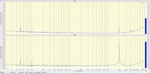
Yes, of course. This suppression must be considered.All I can see is that your filter suppresses the 20kHz and also the harmonics above 20kHz ...
😱
I was interested in the coincidence of the results of simulations and measurements. The results of the simulation were confirmed by several harmonics.
I can't hear the second harmonic of the signal of 20 kHz and above. So I don't see much sense to measure harmonics above.
I do not hide these models. 🙂 I opened several topics, you find there a lot of the models. On the basis of these models were built good amplifiers.Could you please post the LTspice *.ASC files for one of your <0.000,3% THD20k amps?
I'm sure many of us would like to have a play with such good circuits and this would be a great convenience as well as saving a lot of time getting it to work 🙂
If you have the SPICE models for the devices, we would be even more grateful.
For example:
Attachments
Last edited:
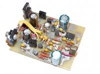
This model amplifier, with which I began. This scheme is as simple and just as effective.
2 ppm @ 20k @150 W @ 8 Ohm according to the simulation, 3 ppm according to measurements. 🙂
2 ppm @ 20k @150 W @ 8 Ohm according to the simulation, 3 ppm according to measurements. 🙂
Attachments
Last edited:
This model amplifier, with which I began. This scheme is as simple and just as effective.
2 ppm @ 20k @150 W @ 8 Ohm according to the simulation, 3 ppm according to measurements. 🙂
Thx! I try to ask again: how do you measure the 3ppm THD20k@150W8R? With the filter shown be4?
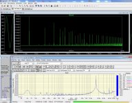
3ppm is 0.000,3%. This value can be measured without a filter and with a filter, but, of course, seen only two or three harmonics.
The photo - comparison of simulation and measurements for this amplifier.
H2 has a delta of -102dB
H3 has a delta of -85dB
IMHO this is far away from 3ppm ... it smells like >50 ppm.
Maybe I'm completely wrong - maybe one can do a calculation?
- Home
- Amplifiers
- Solid State
- Bob Cordell's Power amplifier book