For gyrators i need buffers, which do not snip off a gain fraction, as emitter,source,cathode-followers do, driving loads of say 10KOhms. Gain a bit too hi is o.k.(, tho it complicates calculations, which are yet done by LTspice), but gain a bit too lo kills resonance Quality. I also want to be discrete, just as the computer i am typing this with is so discrete. Finally i do not understand, why one should use power supply voltage over single 12V for home audio, many devices of which cannot stand much signal voltage anyway, unless one adds protection diodes and resistors.
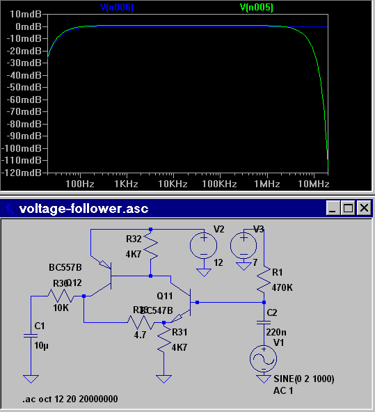
I used 47R instead of 4R7 resistor and easily got a Q of 10. If a loudspeaker has resonances of much greater Q it ain't usable anyway. For load resistances smaller than 10KOhms, all resistors should be scaled down, at least if swing must be large. This circuit must not have capacitive load. Build the circuit as small as the top limb of your finger and place a 100nF ceramic decoupling cap across 12V.
I used 47R instead of 4R7 resistor and easily got a Q of 10. If a loudspeaker has resonances of much greater Q it ain't usable anyway. For load resistances smaller than 10KOhms, all resistors should be scaled down, at least if swing must be large. This circuit must not have capacitive load. Build the circuit as small as the top limb of your finger and place a 100nF ceramic decoupling cap across 12V.
Attachments
Last edited:
Interesting study of a single stage impedance buffer.Finally i do not understand, why one should use power supply voltage over single 12V for home audio, many devices of which cannot stand much signal voltage anyway, unless one adds protection diodes and resistors.
For my mixer I use +18 v wall transformer power supply with center analog ground from 7.5v zeners; it is totally adequate.
For power amp I use a single 70 v power supply. Classical music can have 60+ db volume variation, if properly recorded. 1812 Overture for example. I listen at average volume about 1 v on 8 ohm speakers. +60 db, 2^6 times that, 64* , is 64 volts. The cannon shot will probably be 30 or 40 v max with MJ15003G (high gain) output transistors. I use 2n5401 and D44R2 to stand high voltage, TIP41/42C for drivers. Drivers are soon to be MJE15028/29 next iteration. Tinkly bells are a bit frequency limited, although top octave piano sounds good.
Up to now my best 1812 overture is on a LP, so 55 db variation max, so 40 v is pretty real.
Last edited:
Hi Indianajo, i do not understand this calculation. Plus one Bel is defined as ten times power, so two Bel is ten times amplitude, and six Bel thousand times amplitude.+60 db, 2^6 times that, 64* , is 64 volts.
If i calculate dynamic range and power supply voltages, i do it like this:
* Which impedance have my speakers, and which power can and occasionally should my speakers take? Say 8 Ohms and 20 Watts.
* Which voltage is this? (8*20)^(/2) = nearly 13 Volts RMS.
* Power amplifier must have supply of at least peak-to-peak voltage, which is 2*2^(1/2)*13 = around 40 V DC.
* Which small-signal voltage is common? 1V RMS. Hence a power amp gain of 26dB, which is around 20, is good. The preamplifier needs a power supply of at least peak-to-peak signal voltage, which is 2.8V, plus 1V for transistor and resistor losses in each up and down swing, say 5V DC altogether. This is a safe voltage.
* Noise introduced by amplifiers of small gain and not too hi source resistance is negleglible. 470Kohms input resistance shown above is mostly shortcut by the input capacitance, and gyrator noise gets into signal output only within the resonance band.
* Let us have some fun and raise supply voltage to 12V. Now all buffer outputs must be able to swing close to rails, for else input transistor bases might get too hi or lo voltage. So a buffer with 4K7 work resistance must drive a load resistance of at minimum 10KOhm.
* Else, we need to add input protection diodes and resistors. Not a bad idea anyway, considering that equipment like analogue telephones, recording studio and hi-end gear may output dozends of Volts, usually at most 48Vpp, tho ISDN works with 110Vpp.
Well you're right, powers of 10, not powers of 2.
Power db is 10log(p2/p1), So 40v on 8 ohm speaker is (v^2)/Z=1600/8=200W. 1 v on speaker is 1/8 or .125 W. P1/P2 is 1600, log is 3,2, decibel is 32. Not enough headroom for 60 db music source with 70 v supply with soft music at 1/8 watt.
Your spice of 2 transistor buffer is interesting, but the main problem with these single ended circuits is operating power stability over temperature. Which spice doesn't address. If the operating point gets out of center, it starts clipping. There are long temperature analyses of three resistor biasing arrangements of single transistors in the 1974 book I bought, Solid State Devices: Analysis and Application William D. Cooper. But what mostly people do is use the op amp circuit, which stabilizes gain over temperature to Rf/Ri. Rf is feedback resistor and Ri is input resistance.
I use single ended circuits in my power amp for lower wire count hand wiring, but I stabilize temperature with a fan, not some fancy 3 resistor bias arrangement. My mixer is full or op amps.
I have a music source that can go up to 7 vac, the earphone jack of a FM radio, so my 15 v power supply mixer allows me to attenuate that to a 1.6 vac signal max into my power amp smoothly with no clipping. I thought +-15 v power supplies was a bit of overkill, especially as since the 17vct transformer my mixer came with was causing a lot of hum in the mag phono crcuit. I used a 18vdc race car wall transformer external to the case.
Thanks for listening.
This circuit is stable at any temperature of fluid water at sea level, Indianajo. DC gain is 1, so the only things changing with temperature are current gain, which rises a bit with temperature and determines voltage drop over 470KR bias resistor, and base,emitter-diode threshold voltage, which is 0.6V at room temp and falls by 25mV per 10°C temp rise.
At 1/8 W, say -9dBW, you have already 7 Bel dynamic range, if your speakers have a sensitivity of 79dB/W. Plus 32dB = 111dB.
At 1/8 W, say -9dBW, you have already 7 Bel dynamic range, if your speakers have a sensitivity of 79dB/W. Plus 32dB = 111dB.
* Which small-signal voltage is common? 1V RMS.
Actually, 2Vrms at 0dbfs is the most common value today with CD players, DACs and decent soundcards. But smartphones output can be as low as 0.5Vrms.
More than a single 12V PS is very useful as soon as you start to add EQ to your system.
Hi,
i think, that standard output of CD players is 2Vpp, which is 0.7Vrms. I read this in service manuals or datasheets and measured it at least once. Also, output of CD players does not appear to be greater than output of analogue home-use tape recorders, which put out a 0dB voltage of 0.3Vrms and are usually driven to +6dB peak.
On every EQ with more than +6dB gain i have a sticker "forbidden to wifes".
You might add DJs as well to the wifes😀Hi,
i think, that standard output of CD players is 2Vpp, which is 0.7Vrms. I read this in service manuals or datasheets and measured it at least once. Also, output of CD players does not appear to be greater than output of analogue home-use tape recorders, which put out a 0dB voltage of 0.3Vrms and are usually driven to +6dB peak.
On every EQ with more than +6dB gain i have a sticker "forbidden to wifes".
i think, that standard output of CD players is 2Vpp, which is 0.7Vrms.
No it is 2V RMS max. ....
i think, that standard output of CD players is 2Vpp, which is 0.7Vrms. I read this in service manuals or datasheets and measured it at least once.
No, I confirm 2Vrms. Let's take some random stuff:
denon dcd-520: 2VRMS
marantz cd6006: 2,2V RMS
pioneer u0-5: 2.4 Vrms
Cambridge DacMagic XS: 2vrms
dac magic 100: 2.3V rms
I thank you. I have seen output stage of a story CD player built on +5V and outputting 2Vpp at 0dB, and it makes sense, because it fits into 5V, and because older analogue home equipment and virtually all home amplifiers run best with that level. TTL bipolar logic gates use +5V, because at that voltage there is much less chance of destruction. Use of voltages worthy of power amps for pre-amps is ill.
Last edited:
I thank you. I have seen output stage of a story CD player built on +5V and outputting 2Vpp at 0dB, and it makes sense, because it fits into 5V, and because older analogue home equipment and virtually all home amplifiers run best with that level. TTL bipolar logic gates use +5V, because at that voltage there is much less chance of destruction. Use of voltages worthy of power amps for pre-amps is ill.
That would have ben an non standard device as 2V rms is the standard. For 2V rms you need way more than 5V. Good equipment has at least a +/- 9V PSU to have enough headroom. Some opamps also can not swing to rail voltage. Often +/- 12V is used just to be safe. It has almost no negative side effects. Having too low voltages does have negative side effects.
5V TTL voltage is for the digital part. With recent stuff it is 3.3V or less. Please see this as an other area. Your output stage must be able to produce 2V rms AC with reference to 0V so it has to swing positive and negative. I think this has been standard since the introduction of CD in 1980 That is a long time ago ! The only CD player I know that had 5V for the output stage was the Telefunken CD300 and it even had +/- 5V. It was not a very good device. Power amplifiers have been adapted to 2V rms for 36 years..... any modern DAC or amplifier or whatever is "2V rms capable".
In car audio the standard is even 4V rms since some time: http://www.bcae1.com/preoutv.htm
I see you make some assumptions but one of the first posts in this thread showed you why these higher voltages are chosen. Check schematics and service manuals and you will see similarities for a reason. Of course you can swim against the stream but this time it won't bring much.
Last edited:
I did see a +/-5 V analog supply on some late-'90s CD player once (a Sony maybe?). That's just about good for 2 Vrms plus a bit of headroom for intersample-overs when using 5532s or the like. You'd probably have to run those inverting to avoid common mode effects though.
My keyboard has a +5V analog supply for its DAC output stage (uses a NJM4580), but that's not exactly super high dynamic range to begin with and needs to be able to run on 6 alkaline cells including the dropout of an ordinary 78x05 type regulator.
My keyboard has a +5V analog supply for its DAC output stage (uses a NJM4580), but that's not exactly super high dynamic range to begin with and needs to be able to run on 6 alkaline cells including the dropout of an ordinary 78x05 type regulator.
Last edited:
As we say here: "exceptions confirm the rules" 🙂
2Vrms means 5.7 V peak-peak.... With only +/- 5V and NE5532 we need to take into account that NE5532 can swing only rail voltage - 2V so with +/- 5V we can swing max. to +/-3 V. This makes 6V peak-peak and is below 5.7 ... This is even calculated mildly as some samples can only swing rail voltage -3V (see datastaat for worst case data)......which means 4V peak-peak which will cause nice sound quality 😉
My math can be off but I think it is clear that a 2Vrms output stage will not work adequately with +/- 5V supply voltage and "normal' bipolar opamps.
* If I had such a mediocre DAC I would replace the 7805 for an ultra low drop 6V type. Easy peasy. First check current draw in the situation as it is now, then choose an ultra low drop type with lowest noise specs. That 7805 and NJM4580 are only there for one reason. As it feeds only the output stage current draw will be way under 50 mA. If the 7805 is an SMD type then things are even more simple. An 7805 has a typical dropout voltage of 2V so minimum input voltage is 7V. Alkaline batteries are 1.5V so 6 of them will make 6 x 1.5V = 9V. I think they will be 1.2V as they are depleted. That makes 6 x 1.2V = 7.6V. You can use a regulator adjusted to 7V if you choose a type with dropout voltage below 0.3V ! Bias current of modern LDO regs is also lower.
Choice for 7805 and 5V for the output stage are to be classified under "design errors because of cost cutting".
Last edited:
This only works if the DAC chip has its own regulator (modern DAC chips often work with 3.3V).
Anyway, you will have longer battery life and better sound quality as a bonus. If other chips are also fed with a 7805 then changing that reg to an ultra low drop LDO types would give you maximum possible battery life for sure. You would be able to use the keyboard with batteries that you would now have to replace... If you have some doubts then a 6V ultra low drop reg is guaranteed to work OK as the current 7805 will be in trouble with batteries going to 1.17V so a total of 7V. Let's say you choose a 0.3V dropout type. That would mean batteries can be as low as 1.06V (so a total of 6.36V) and the output stage will still work OK. I never would have thought that I would give advice on modding a keyboard but here you go 😀
Back to the topic ?!
Last edited:
As you may have guessed, this is a rather low-end model (Yamaha PSR-E323). Higher-end ones do (surprise!) feature LDOs. It does take quite a while until you get some decently high supplies though (S7xx series). Anyway, amplifier hiss on the headphone out is bothering me more on this one, I'm always using it with an attenuator to get rid of that. Seems like the old power amp IC won't support an awful lot less than 35.5 dB, and a 100 ohm series resistor provides too little attenuation for 300 ohm cans.
I do think the likes of NE5532 can swing closer than 2 V. Samuel Groner got a bit over +22 dBu of clipping level out of the TI part on +/-15 V (even on 600 ohms), pointing towards at least a +/- 13.8 V swing. 1.2 V is about what I would have expected, too. I think 4580s are similar. The old Signetics NE5532 is a bit weaker but still manages at least +21 dBu, or +21.5 on a 10 kOhm load. That's more like 2.0 V indeed. Interesting.
I do think the likes of NE5532 can swing closer than 2 V. Samuel Groner got a bit over +22 dBu of clipping level out of the TI part on +/-15 V (even on 600 ohms), pointing towards at least a +/- 13.8 V swing. 1.2 V is about what I would have expected, too. I think 4580s are similar. The old Signetics NE5532 is a bit weaker but still manages at least +21 dBu, or +21.5 on a 10 kOhm load. That's more like 2.0 V indeed. Interesting.
Thinking or checking ?
http://www.njr.com/semicon/PDF/NJM4580_E.pdf
1.2 to 2V. With many opamps it depends on output load. With only 5V available things are a bit more critical.
So instead of solving the hissing it is attenuated ?! You don't work at VW do you ? 🙂 A series resistor does not really improve things. Solutions lay in front of you. Upping the PSU as indicated and using a well decoupled lower noise opamp (one that can take single power supply) that can swing to rail voltage would be prefered. Problems are best solved at the root. The design obviously has some issues preventing it from performing really good. At least I take hissing and lack of headroom as not good. Things might possibly improve a lot by replacing just one regulator IC and one opamp so at very acceptable costs... If you get famous by improved sound quality and get to "Rock am Ring" I want an autograph OK ?
1. Do you have a schematic ?
2. What DAC IC is being used ?
3. Does the DAC chip have a separate regulator ?
4. Is the headphones output via a separate opamp ?
5. What 2 x 2.5W power amp IC is being used ?
6. Pictures do help !
This thread is derailing seriously but I don't mind. Maybe OP and others do mind and should we ask for this posts to be in separate thread "Improving the Yamaha PSR-E323 keyboard".... It is up to you.
Last edited:
Take for instance LM3886, datasheet says gain of 20 and input resistance of 22KR. With 70V supply this means input of 3.5Vpp. Having a one-stage emitter follower on +5V with 2KR2 work and 220R output series, maximum peak-to-peak output with DC is 0.7 to 4.3V, so after AC coupling it can just saturate the LM3886.
Do you always want to put the volume control at over 12 o'clock position ? Please keep to 2V rms standard and life is simpler. Headroom is good. Too much gain is not nice but calculating to the minimum is another thing.
If you use your circuit with symmetrical power supplies you can have more headroom and 2V rms standard. I don't think you can get rid of the caps. It should be able to drive 600 Ohm loads too IMHO. A JFET input opamp buffer with +/- 12V power supplies can do better with less parts and no coupling caps. I don't see the point in using too low power supply voltages. I once had a preamp that had +/- 30V PSU and that one was truly exaggerated. It could indeed destroy stuff. A preamp/buffer with too low power supply voltages one can have serious distortions too from clipping which might be negative to the power amp and speakers (compared to a preamp that does not clip but simply overdrives the power amp = less clipping).
If you use your circuit with symmetrical power supplies you can have more headroom and 2V rms standard. I don't think you can get rid of the caps. It should be able to drive 600 Ohm loads too IMHO. A JFET input opamp buffer with +/- 12V power supplies can do better with less parts and no coupling caps. I don't see the point in using too low power supply voltages. I once had a preamp that had +/- 30V PSU and that one was truly exaggerated. It could indeed destroy stuff. A preamp/buffer with too low power supply voltages one can have serious distortions too from clipping which might be negative to the power amp and speakers (compared to a preamp that does not clip but simply overdrives the power amp = less clipping).
Last edited:
At neits volume points to the left.
It gets the truely easier, the less complexity there is. No ICs, no MOSFETs. You will start to apprechiate simple things such as a capacitor, a resistor and a transistor and be able to build all basic communications stuff above and belo noise just from these parts.
It gets the truely easier, the less complexity there is. No ICs, no MOSFETs. You will start to apprechiate simple things such as a capacitor, a resistor and a transistor and be able to build all basic communications stuff above and belo noise just from these parts.
- Status
- Not open for further replies.
- Home
- Source & Line
- Analog Line Level
- simplest discrete really-unity gain buffer