Let's go to see what we have up to now.
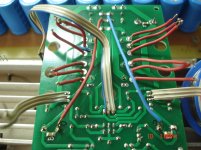
1)Tracing the signal gnd network.
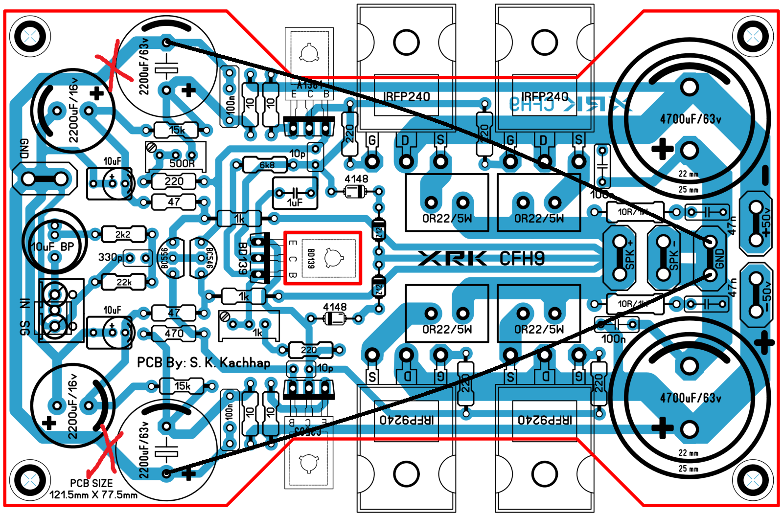
Probe between A,B points.
2)Measuring the same points A,B
Yes, that's it

CFH9
Shaan,we have continuity!
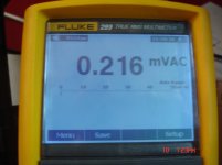
1)I have cut two traces.
2)Now look what is the measurement.(exactly same when testing leads shorted)
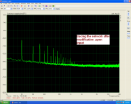
3)Tracing between A,B after the modification.
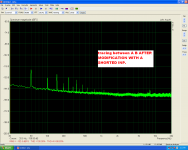
4)>> >> >> >> WITH A SHORTED INP.
Shaan,we have continuity!
1)I have cut two traces.
2)Now look what is the measurement.(exactly same when testing leads shorted)
3)Tracing between A,B after the modification.
4)>> >> >> >> WITH A SHORTED INP.
Attachments
Last edited:
Hi guys,
I went into the lab to try to see what I am getting and why it seems to work. I have been using a cap multiplier all along so I have very little (almost zero) supply rail ripple. This is the Juma's Easy Peasy Cap Mx (IRFP240/9240 and 4700uF with 470uF caps). The amp has no hum. But when I bypassed the Cap Mx and go directly from the CRC PSU (2x9600uF caps per rail), I can hear hum. So this was why I did not hear it. I just did not notice it when I quickly tested before without the Cap Mx.
So in the absence of a solution to this, I would recommend building the very easy to make cap multiplier to temporarily solve the issue. But if you guys can figure out an easy or clever way to remove the hum with some sort of jumper or ground strap that would be great.
The Juma Cap Mx adds 50dB of PSRR, which essentially makes this a non issue. Hope that helps.
Hi valery,
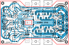
Could shorting ground lifter solve the issue? If no than Sonal layout has the same issue see picture under.
This issue can be solved with cutting two tracks and soldering two wire : C14 to C7 and C16 to C6 under board.
In fact all this make sens for further routing job.
Marc
Could shorting ground lifter solve the issue? If no than Sonal layout has the same issue see picture under.
This issue can be solved with cutting two tracks and soldering two wire : C14 to C7 and C16 to C6 under board.
In fact all this make sens for further routing job.
Marc
Attachments
Shaan,we have continuity!
1)I have cut two traces.
2)Now look what is the measurement.
Nice work Thimios! Can you show which trace to cut? I don't see it in photo.
Hi guys,
I went into the lab to try to see what I am getting and why it seems to work. I have been using a cap multiplier all along so I have very little (almost zero) supply rail ripple. This is the Juma's Easy Peasy Cap Mx (IRFP240/9240 and 4700uF with 470uF caps). The amp has no hum. But when I bypassed the Cap Mx and go directly from the CRC PSU (2x9600uF caps per rail), I can hear hum. So this was why I did not hear it. I just did not notice it when I quickly tested before without the Cap Mx.
So in the absence of a solution to this, I would recommend building the very easy to make cap multiplier to temporarily solve the issue. But if you guys can figure out an easy or clever way to remove the hum with some sort of jumper or ground strap that would be great.
The Juma Cap Mx adds 50dB of PSRR, which essentially makes this a non issue. Hope that helps.
Solution could be cutting tracks between C14-C3 and trancks between C16-C2 and soldering 2 wire : C14 to C7 and C16 to C6 and you are than according to shaan and other right recommandations. i think i will do this modification.
Marc
So in the absence of a solution to this...
Wait wait... 😛
We're getting there! 🙂
Solution could be cutting tracks between C14-C3 and trancks between C16-C2 and soldering 2 wire : C14 to C7 and C16 to C6 and you are than according to shaan and other right recommandations. i think i will do this modification.
Marc
You mean like this?

Attachments
Hi valery,
Could shorting ground lifter solve the issue? If no than Sonal layout has the same issue see picture under.
This issue can be solved with cutting two tracks and soldering two wire : C14 to C7 and C16 to C6 under board.
In fact all this make sens for further routing job.
Marc
Hi Marc,
In this layout by Sonal there's no ground lift resistor - in this case it will work fine.
CFH9
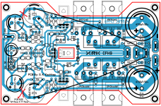
Guys sorry but the good news ended here.
Look what output tracing without any signal(shorted inp.)after the modification.
Guys sorry but the good news ended here.
Look what output tracing without any signal(shorted inp.)after the modification.
Attachments

Last edited:
Hi Marc,
In this layout by Sonal there's no ground lift resistor - in this case it will work fine.
So Valery according your word solution is more simple than cutting tracks and adding wire.....and consist in simple shorting ground lifter...
Marc
Attachments
Last edited:
Guys sorry but the good news ended here.
Look what output tracing without any signal(shorted inp.)after the modification.
Hi Thimios,
What modification are your talking about?
Marc
For the single-board amplifier, I recommend 3 ground points:
1) Power ground in the end of the board close to the output - main rails decoupling goes there.
2) Front-end ground - front-end decoupling and other front-end ground references go there.
Both grounds are connected to PSU main ground by separate wires.
3) Signal ground with only the input resistor and NFB divider connected to it, with ground-lift resistor between this point and the front-end ground.
this configuration is tested with very good results.
Hi Thimios,
What modification are your talking about?
Marc
This way but the problem is still here🙁
Attachments
[/CENTER]
Yes!
A bit better is this.
Yes, you also need to reduce the value of decoupling resistor to, say, 2R2.
Two 47R resistors in parallel (parts of the feedback network) are connected to it - 10R is way too much.
Do you mean that c3,c2 must be on a separate gnd too?For the single-board amplifier, I recommend 3 ground points:
1) Power ground in the end of the board close to the output - main rails decoupling goes there.
2) Front-end ground - front-end decoupling and other front-end ground references go there.
Both grounds are connected to PSU main ground by separate wires.
3) Signal ground with only the input resistor and NFB divider connected to it, with ground-lift resistor between this point and the front-end ground.
this configuration is tested with very good results.
Please Valery mark all the changes to the picture on post #617
Last edited:
- Home
- Amplifiers
- Solid State
- CFH7 Amp