Ok,thanks 😉The supply is fine, but seeing the output spectrum with the input shorted may give us a clue where to look next.
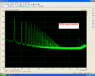
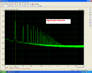
Here is the FFT with a shorted input.The supply is fine, but seeing the output spectrum with the input shorted may give us a clue where to look next.
Attachments
Last edited:
...It is a clear audible hum... It isn't a power supply problem...
The intention for the dedicated input ground is to provide the input section the cleanest reference, direct from the main PSU ground.
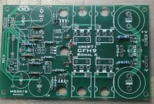
In the CFH9 PCB I see the C14 and C16 terminated to the input side ground. These capacitors are decouplers, doing a dirty job of cleaning the VAS/Input supply off some ripple. They do not suck/absorb the ripple current, they pass it to ground and get a tiny bit charged while doing that.
Ideally that ripple current flows to any connected ground without problem if the trace was a superconductor, but in our case it is a very not-superconducting copper, having still some minute resistance. Now add with it the 10R to the ohm's law equation (ignoring 0.7V clamp by the two anti-parallel diodes). If there is any current into any resistance there shall be born a Voltage. This voltage pollutes the input ground with its most fundamental component, i.e. the 50Hz(or 60Hz) ripple. Obvious in the spectrum traces.
IME, the solution is to route all the decouple capacitors (even the small ones) to the PSU side ground and keep the input-feed ground for only input.

Attachments
Very good catch!The intention for the dedicated input ground is to provide the input section the cleanest reference, direct from the main PSU ground.
In the CFH9 PCB I see the C14 and C16 terminated to the input side ground. These capacitors are decouplers, doing a dirty job of cleaning the VAS/Input supply off some ripple. They do not suck/absorb the ripple current, they pass it to ground and get a tiny bit charged while doing that.
Ideally that ripple current flows to any connected ground without problem if the trace was a superconductor, but in our case it is a very not-superconducting copper, having still some minute resistance. Now add with it the 10R to the ohm's law equation (ignoring 0.7V clamp by the two anti-parallel diodes). If there is any current into any resistance there shall be born a Voltage. This voltage pollutes the input ground with its most fundamental component, i.e. the 50Hz(or 60Hz) ripple. Obvious in the spectrum traces.
IME, the solution is to route all the decouple capacitors (even the small ones) to the PSU side ground and keep the input-feed ground for only input.
In any case the VAS current decoupling capacitors aren't these,those are for input decoupling .
Thanks Shaan!
Last edited:
Here is the FFT with a shorted input.
Wow... rather wide-bandwidth. I agree with Shaan - it may be related to the grounding scheme.
Can you try to catch it with the oscilloscope?
It will have some millivolts amplitude and will match 50Hz timing pattern, being more complex than a sine wave.
Wow... rather wide-bandwidth. I agree with Shaan - it may be related to the grounding scheme.
Can you try to catch it with the oscilloscope?
It will have some millivolts amplitude and will match 50Hz timing pattern, being more complex than a sine wave.
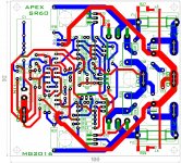
i will try to rearange the traces
@vzaichenko
I think the harmonics are due to the sawtooth nature of the ripple.
@thimios
Try tracing the two ends of the 10R+diode network.
I think the harmonics are due to the sawtooth nature of the ripple.
@thimios
Try tracing the two ends of the 10R+diode network.
@vzaichenko
I think the harmonics are due to the sawtooth nature of the ripple.
@thimios
Try tracing the two ends of the 10R+diode network.
sorry i don't undertand this .
Do you mean to short the network?
Do you mean to short the network?
No. I mean to connect the ground clip to B and the probe to A, i.e. to see what is happening between these to points when the amp is on.
Attachments

Last edited:
No. I mean to connect the ground clip to B and the probe to A, i.e. to see what is going between these to points when the amp is on.
the scope probe?
the scope probe?
On ARTA. Trace this point like you trace the output. 🙂
On ARTA. Trace this point like you trace the output. 🙂
Ok got it.
Agreed............................ the solution is to route all the decouple capacitors (even the small ones) to the PSU side ground and keep the input-feed ground for only input............
That signal return with all those contaminating connections cannot work !
I agree with the way C14/16 are routed i read some advice in this way for decoupling ground return. Even These C14/C16 are not carring high Amp current. 4700uf in OPStage ahave their own return. And even X have no hum in his CFH9 nor in CFH7 that have dirtiest return route.
Marc
Marc
Hello Idefixes.
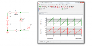
Take a look. I tried to illustrate the effect as simply as I could.
Showing only the positive half, the negative is the same, only opposite polarity.
V1 is our positive supply at 50V.
V2 induces a 100mV sawtooth wave over V1, making the voltage on the left of R1 a sum of V1 and V2. Almost simulating typical rectified PSU output.
C1 simulates C14 in CFH9 PCB.
l1 simulates input segment current draw (2mA is a typical value).
R2 simulates the 10R resistor of the diode+resistor network (diodes not drawn as not necessary for the purpose here).
The green trace shows the ripple current flowing through C1 (C14 in CFH9). Remember that this current also flows through R2 to ground.
The red trace shows voltage at right side of R2 (Point A in the last pic I uploaded). This voltage is a direct result of the ripple current flowing through R2. This is the problem because this exact sawtooth voltage is the "ground" presented to the input stage and it shows a 60mV amplitude while it should be a straight line (i.e. 0V AC).
The input does not care what the problem is, it will take this voltage as part of input signal (even when input pins are shorted) and amplify it according to the amplifier's gain. As a result it finds its way to output.
Attachments
Hello Idefixes.
Take a look. I tried to illustrate the effect as simply as I could.
Showing only the positive half, the negative is the same, only opposite polarity.
V1 is our positive supply at 50V.
V2 induces a 100mV sawtooth wave over V1, making the voltage on the left of R1 a sum of V1 and V2. Almost simulating typical rectified PSU output.
C1 simulates C14 in CFH9 PCB.
l1 simulates input segment current draw (2mA is a typical value).
R2 simulates the 10R resistor of the diode+resistor network (diodes not drawn as not necessary for the purpose here).
The green trace shows the ripple current flowing through C1 (C14 in CFH9). Remember that this current also flows through R2 to ground.
The red trace shows voltage at right side of R2 (Point A in the last pic I uploaded). This voltage is a direct result of the ripple current flowing through R2. This is the problem because this exact sawtooth voltage is the "ground" presented to the input stage and it shows a 60mV amplitude while it should be a straight line (i.e. 0V AC).
The input does not care what the problem is, it will take this voltage as part of input signal (even when input pins are shorted) and amplify it according to the amplifier's gain. As a result it finds its way to output.
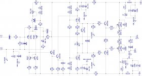
Hi shaan thanks for explanation. All routing job after CFH9 my SR60 layout under (red tracks) C2 isn't solder for separated ground. What i can say is that the major parts of layout i can see on diyaudio doesn't care from as all ground are together even Peeceebee v1.1 is routed that way....my verstatil (VSSA with BJT output) too but silent dead....
Marc
Attachments
Last edited:
...What i can say is that the major parts of layout i can see on diyaudio doesn't care from as all ground are together even Peeceebee v1.1 is routed that way....my verstatil (VSSA with BJT output) too but silent dead...
Of course.
Terminating all ground paths in a single point on amplifier PCB is great for reducing chance of supply noise getting into signal if thick power cables are used and cable length is kept to a minimum.
But providing the input ground directly from PSU ground is a step further and eliminates all possibilities of anything from the supply rails getting into signal ground. This is why V2 has it and it is more immune to supply rail noises than V1.1 even if thin and long cables are used.
Happy building.
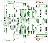
CFH9
Let's go to see what we have up to now.
1)Tracing the signal gnd network.
Probe between A,B points.
2)Measuring the same points A,B
Let's go to see what we have up to now.
1)Tracing the signal gnd network.
Probe between A,B points.
2)Measuring the same points A,B
Attachments
Last edited:
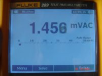
Bingo!
Now short the 10R resistor and do the same traces from output. You should see PeeCeeBee type noise spectrum that you posted earlier in post#565.
Now short the 10R resistor and do the same traces from output. You should see PeeCeeBee type noise spectrum that you posted earlier in post#565.
Hello Idefixes.
Take a look. I tried to illustrate the effect as simply as I could.
Showing only the positive half, the negative is the same, only opposite polarity.
V1 is our positive supply at 50V.
V2 induces a 100mV sawtooth wave over V1, making the voltage on the left of R1 a sum of V1 and V2. Almost simulating typical rectified PSU output.
C1 simulates C14 in CFH9 PCB.
l1 simulates input segment current draw (2mA is a typical value).
R2 simulates the 10R resistor of the diode+resistor network (diodes not drawn as not necessary for the purpose here).
The green trace shows the ripple current flowing through C1 (C14 in CFH9). Remember that this current also flows through R2 to ground.
The red trace shows voltage at right side of R2 (Point A in the last pic I uploaded). This voltage is a direct result of the ripple current flowing through R2. This is the problem because this exact sawtooth voltage is the "ground" presented to the input stage and it shows a 60mV amplitude while it should be a straight line (i.e. 0V AC).
The input does not care what the problem is, it will take this voltage as part of input signal (even when input pins are shorted) and amplify it according to the amplifier's gain. As a result it finds its way to output.
Shaan - makes a lot of sense. I have just realized that all the rails decoupling is connected to the signal ground here - this is definitely a mistake.
Guys, only the input resistor and feedback resistor can be connected there for the ground lift to work properly. Also - in CFA designs, the feedback network is rather low-inpedance, so in CFA front-ends I either don't use the lifted ground, or use a rather low-ohm resistor (4.7...2.2 ohm).
- Home
- Amplifiers
- Solid State
- CFH7 Amp