Hi Andrew - thanks. Very useful. How should I work out the A/C snubbers around the transformer? Is there a basic set of figures for a 400VA / 40mF centre-tap arrangement? I'll have access to lab at work so I can measure inductance and picofarad capacitances.
Patrice - wow. Just wow.
My proposed layout is shown attached. Good to hear that it's not mad to proceed sans PCB.
Patrice - wow. Just wow.
My proposed layout is shown attached. Good to hear that it's not mad to proceed sans PCB.
Attachments
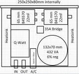
Hmm I am struggling to find room for the B41550 - they're just so fat. Unless... I go for 4x 22,000µF (instead of 8x 10,000µF, which won't fit).
Is there anything wrong with using just one 22 mF reservoir cap on each rail, with a 35A integrated bridge? I have heard it said that using single devices >10 mF is pushing it. Or something.
So here's the choice:
4x B41550 22 mF OR
8x B41560 10 mF. These are 36mm not 52 diameter and generally inferior.
Is it ok to use such large caps with a pair of 35A integrated bridges? Surely 8x10 mF caps will be pretty much equivalent to the 4x 22 mF single unit anyway from an inrush POV.
Thx for your patience with my electronics 1.0.1.
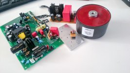
for Switching power supply
film capacitors is definitely improving
If you have the budget
film capacitors is definitely improving
If you have the budget
Attachments
-
 14589968_3364239028039_6039428650609605314_o.jpg360.7 KB · Views: 1,226
 -
 14615835_3364241548102_7756788131485291087_o.jpg363.2 KB · Views: 1,196
 -
 14853073_3382339000527_8686748139069228003_o.jpg196.8 KB · Views: 1,171
 -
 14853054_3395384566658_6744484636311615277_o.jpg343.6 KB · Views: 1,174
 -
 14883548_3395365606184_2356410838174204351_o (1).jpg224 KB · Views: 466
Last edited:
(according to Hagerman (figure 7): http://www.hagtech.com/pdf/snubber.pdf)
I have often seen snubbers omitted (Power Supply for Power Amplifiers) or applied across the DC rails, but I have not seen snubbing done across the diodes and filter caps in practice. Since Hagerman seems to know what he's talking about, why is it not more common to see this snubbing arrangement?
He sure does. They should be. John Swenson uses snubbers in his PSUs - c.f. the Uptone Audio JS-1 or his old SBT DIY PSU.
I am also using them in all my DIY Linear Reg PSU designs (e.g. for my Modular Synth and to replace SPMSs in the audio reproduction gear).
Years ago, I tried and found these caps excellent. Then this was a "husband and wife" company that that would put their products before life as it was.
They are probably in the same vain as Nelson with his amps. Check them out maybe worth qualifying as an audio conforming product. Aluminium Electrolytic Capacitors - EnglischEnglisch | HIGH QUALITY CAPACITORS
They are probably in the same vain as Nelson with his amps. Check them out maybe worth qualifying as an audio conforming product. Aluminium Electrolytic Capacitors - EnglischEnglisch | HIGH QUALITY CAPACITORS
A mom and pop company can afford there own manufacturing plant? More likely they put there name on Sprague or Panasonic caps and boost the price.
A mom and pop company can afford there own manufacturing plant? More likely they put there name on Sprague or Panasonic caps and boost the price.
Some people actually start companies from grass roots and make a success of it. I know I did except there was no mom involved.
 That is basically the difference between working for somebody for 25 years or building your own business for 25 years based in innovation instead of do as you'r told. We can name a lot of companies that starts from a husband and wife team, guy and his mate working in their kitchen and ends up world leader products.
Last edited:
I doubt anyone can manufacture state of the art capacitors in there garage. Meaning reasonable performance and sizes for large capacitors. Its almost like saying I'm making transistors in my basement.
I like the look of these Krummer caps... some useful can sizes too. Is anybody else using 18 or 20 mF caps in a power supply? Is this 'too big'?
I know, ridiculous! There will be people claiming they can make valves next! diyvacuumtubes.com 😀I doubt anyone can manufacture state of the art capacitors in there garage. Meaning reasonable performance and sizes for large capacitors. Its almost like saying I'm making transistors in my basement.
Is anybody using RC filter with reservoir caps? Even a small resistance such as 2-5 mOhms in series on the power rails would flatten anything above 100 kHz with maybe 500mW dissipated and a fraction of a Volt dropped. Seems like a good trade. Just need to find a really bad conductor to act as 2 mR resistor... rusty nail? Piano wire?
My gut feeling is that a 50mm length of 1mm diameter resistor wire in free air between two big screwcap capacitors should not conduct too much heat back into the caps. Even if it's 20%, thats still only 100mW. The 0V return side would be low resistance bus-bar.
Anybody done this between filter caps? Or alternatively an LC filter?
Last edited:
Do you mean a zobel? R + C?
This is an article published in TNT audio on power supplies:
Solid State Power Amplifier Supply Part 3
The three parts I consider mandatory reading for anyone seriously interested in power amplifier supplies.
The author highly recommends using a 680n + 1R/17W zobel after the electrolytic capacitors.
Hi carl,
No I didn't mean a Zobel. Basic RC filter as shown here:
Filter Circuits with Capacitors
With the Zobel, the R and C are series, both in parallel with the load. With the basic first order LP filter, the R is actually in series on the supply rail not across the load. The C is parallel to the load as in 'Zobel'.
So... clearly the current to the load would have to pass through the resistor in a low-pass RC filter, so it's not practical to try to bring the 3dB point much below 5 kHz. The way I figure it, there's two considerations: inrush and max continuous. I need a beefy enough resistor that it will survive inrush since it's part of the power rail and feeding one big filter cap e.g. 0.01F. Helps reduce cap inrush (very slightly). If my max continuous DC current is 5A, then steady-state power dissipated with a 2 mOhm resistor is 5*5*0.002 = 50 mW. Resistance and power consumption will probably double as it gets hot. 3dB cutoff is at about 8 kHz (cold).
Seems like it's a small price to pay in component count, voltage drop, power and heat to eliminate HF noise. When you connect two big filter caps, why not use a piece of lossy steel instead of copper? (ON THE RAIL SIDE ONLY - ALWAYS USE MINIMUM RESISTANCE ON GROUND SIDE).
What am I missing? I realise LC filter would avoid the loss - might look at that next.
I have been recommending similar to this for what seems like years.Is anybody using RC filter with reservoir caps? Even a small resistance such as 2-5 mOhms in series on the power rails would flatten anything above 100 kHz with maybe 500mW dissipated and a fraction of a Volt dropped. Seems like a good trade. Just need to find a really bad conductor to act as 2 mR resistor... rusty nail? Piano wire?
My gut feeling is that a 50mm length of 1mm diameter resistor wire in free air between two big screwcap capacitors should not conduct too much heat back into the caps. Even if it's 20%, thats still only 100mW. The 0V return side would be low resistance bus-bar.
Anybody done this between filter caps? Or alternatively an LC filter?
an ordinary capacitor input filter used for the smoothing after the rectifier is actually an rC filter.
There should ALWAYS be supply rail decoupling in the amplifier. This is a further C.
You end up with an rCrC when you use a tiny amount of resistance in your wiring between the various elements from transformer to amplifier.
I have recommended using 0.6mm diameter insulated solid core copper hook up wire for the feed to the power amp. This would do for all but the biggest power amplifiers. It never passes enough continuous current to get warm, never mind hot.
This has a negative cost, i.e. it costs less to implement than using big stranded cables for the inter module connections.
Last edited:
I have been recommending similar to this for what seems like years.
Thanks Andrew. I'm listening now!
I ordered 0.8 mm solid wire in the end... a small half-loop of 10 cm between filter caps should give me 2-3 mR and covers me for max output if I use the same to connect to the amp board. The board also has 2x 4700uF too so like you say it's RCRC. Should push any ringing into the floor I hope.
If I use the same wire between the rectifier bridge and first filter cap, then I will have:
Rectifier -> 2 mR -> 10 mF -> 2 mR -> 10 mF -> 2 mR -> 4.7 mF -> Amp i.e. RCRCRC
What's the catch? What's the down-side? Apart from a Watt or so dissipated over each +/- 52V rail.
If I use the same wire between the rectifier bridge and first filter cap, then I will have:
Rectifier -> 2 mR -> 10 mF -> 2 mR -> 10 mF -> 2 mR -> 4.7 mF -> Amp i.e. RCRCRC
What's the catch? What's the down-side? Apart from a Watt or so dissipated over each +/- 52V rail.
Bigger loop area means more efficient aerials to emit emi to infect other stages.
for hook up wire I use
https://www.rapidonline.com/rapid-100m-reel-1-0-6-1-of-each-colour-11-reels-01-0380
available in 11 colours to avoid confusion.
But be careful with all these plastic insulated cables. They do not tolerate high temperatures. Do not wind theminto coils, nor as windings around a transformer core.
For air cored inductors use SWC for enamelled copper wire that is rated from 155°C to >200°C
Hi.
I have a long term project to built a Krell Klone Ksa-50.
So far I have 2 SumR 600VA transformer (2x28Vac).
Next I'm looking for some capacitors for the power supply.
What do you thing about the Kendeil Capacitor.
Maybe something like 2 x 47000 uF per rail (8 totals, 2 per rail x 2 channels).
KENDEIL 47000UF 50V K01. 4x NEW GENUINE KENDEIL 47000UF 50V K01 CAPS FOR KRELL KSA50 NAIM HICAP QUAD AMP! | eBay
There isn't any distribution network here in North America.
But you can find them on Ebay from vendor (Paradise of Hi-end audio components) a member here as diyAudio - View Profile: umut1001
Do you have other suggestion in the same price range, and I would like they be black for esthetic.
Regards
I have been recommending similar to this for what seems like years.
an ordinary capacitor input filter used for the smoothing after the rectifier is actually an rC filter.
There should ALWAYS be supply rail decoupling in the amplifier. This is a further C.
You end up with an rCrC when you use a tiny amount of resistance in your wiring between the various elements from transformer to amplifier.
I have recommended using 0.6mm diameter insulated solid core copper hook up wire for the feed to the power amp. This would do for all but the biggest power amplifiers. It never passes enough continuous current to get warm, never mind hot.
This has a negative cost, i.e. it costs less to implement than using big stranded cables for the inter module connections.
Andrew, I'm not sure I understand where you would put the 0.6mm wire - do you mean using 0.6mm wire between the transformer's secondary AC output and the AC input of the amp board PCB?
I've had bits from 'umut' in the past - no problems at all
Suggest you work out 'the joules' and reconsider the 8 x 47mF for a ksa50 klone (0.36F!) - even I would call that 'overkill' - generally, as the size goes up, the 'speed' goes down (if you accept this so-called 'rule of thumb') - it does seem to be true with the ones I've tried out, like Siemens, Rifa and BHCs, but maybe you want this characteristic in your amp design
I tried out something like this on that 'forerunner' of the F5 (sorry, forgotten the name) and got up to about 60,000uF/rail but then reduced back to 2 x 10mF
Mind you, I could be quite mistaken here - it's happened before!
- Home
- Amplifiers
- Power Supplies
- Best capacitors for power supplies update